You can tell BARR/RJE which PC resources your Barr communications adapter uses on the Interrupt Request, Address, and Loopback Test screen discussed in section 17.1. Because requirements vary by adapter (particularly for the T1-SYNC adapter), see your adapter manual for information about setting the interrupt request, device address, and DMA fields. The screens in this chapter show defaults with no adapter or a Barr SYNC ISA adapter installed.
Section 17.2 describes how to use the loopback test software included with your Barr adapter. Use this test to verify that you properly installed the adapter and that it functions correctly. The loopback test varies slightly from adapter to adapter. See your adapter manual for adapter-specific information about the loopback test.
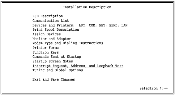
Start at the BARR/RJE Installation Description screen.
Select Interrupt Request, Address, and Loopback Test.
 Hardware Conflicts: Change the Interrupt request, Address
and DMA request
default settings only if you verify a conflict with other equipment in
the PC. If a hardware conflict exists, the software will not function
correctly when you try to start or operate it.
Hardware Conflicts: Change the Interrupt request, Address
and DMA request
default settings only if you verify a conflict with other equipment in
the PC. If a hardware conflict exists, the software will not function
correctly when you try to start or operate it.
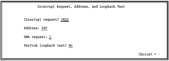
Interrupt request?
Hardware line over which the processor and adapter communicate. The IRQ carries signals to get the processor’s attention when the adapter is ready to receive or send information.
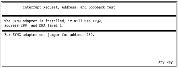
The default setting for the SYNC ISA adapter is IRQ2. You might find an IRQ conflict if you use a LAN adapter because LANs typically use IRQ2. If you verify an IRQ conflict, change the software setting. Other choices are IRQ5, IRQ10, IRQ11, IRQ12, and IRQ15.
Address:
Address for the device.
The address in the software must match the address jumper
setting on the adapter.
The default value on the SYNC ISA adapter and in the software is 280. (If the software and adapter addresses do not match, the choices displayed for the adapter settings will be different from the ones listed in this section.) If the PC detects a conflict, you must change the adapter hardware and software settings. Other choices are 290, 2A0, and 2B0.
DMA request: 1|3|1&3
Channel over which the adapter directly accesses memory. DMA is a time-honored way to achieve high transfer rates between memory and a peripheral device. Special hardware implements 16-bit bus master DMA. The default DMA value is 1. Other choices are 3, 5, 6, and 7.
For the RS232 and V.35 adapters, choose 1, 3, or 1 & 3. The software uses only one DMA channel, either 1 or 3, for half-duplex communications. It uses both DMA channels 1 & 3 for full-duplex communications.
 DMA Priority: During DMA transfers, if another adapter
prevents the SYNC ISA adapter from acquiring the bus in a timely manner,
you might see receive overruns and send underruns (indicated by a magenta
X
on the Communication Scope) when the software operates at high speeds.
As a precaution, install the SYNC ISA adapter with the lowest DMA request
(highest priority) of all adapters in the PC. This prevents other adapters
that inadequately share DMA from affecting performance.
DMA Priority: During DMA transfers, if another adapter
prevents the SYNC ISA adapter from acquiring the bus in a timely manner,
you might see receive overruns and send underruns (indicated by a magenta
X
on the Communication Scope) when the software operates at high speeds.
As a precaution, install the SYNC ISA adapter with the lowest DMA request
(highest priority) of all adapters in the PC. This prevents other adapters
that inadequately share DMA from affecting performance.
Perform loopback test?
The loopback test verifies that the hardware is installed correctly and that the hardware and software settings are correct. The loopback test plug comes with the SYNC ISA cable.
No – Default. Do not perform the test.
Yes – Run this test after hardware and software installation, when you change the settings on this screen, or if you suspect a hardware error. The loopback test performs diagnostics on the synchronous adapter, cable, and modem. Instructions display on the screen for each step. See section 17.2 for detailed information about the loopback test.
After you make your selections and press ENTER, a screen similar to the one below displays additional adapter information. Your screen reflects the settings you selected.
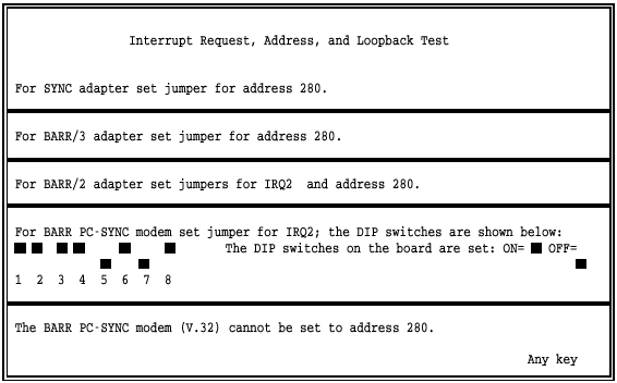
 The BARR/2 and BARR PC-SYNC are older adapters that have been
discontinued.
The BARR/2 and BARR PC-SYNC are older adapters that have been
discontinued.
 Press any key to continue.

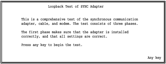
Barr software includes an adapter loopback test, which verifies that the adapter functions properly by performing diagnostics on the synchronous adapter, cable, and modem.
The loopback test consists of three phases:
Phase 1: Adapter installation and settings
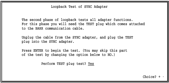
Phase 2: All adapter functions
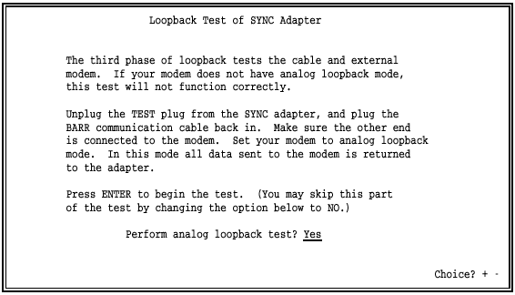
Phase 3: Cable and external modem
Because an internal modem has no modem cable or test plug, phases 2 and 3 do not apply to PC-SYNC internal modems.
You can run Phase 1 without the test plug or a modem connection. This phase verifies that you installed the adapter correctly and that all settings are correct.
Phase 2 requires the test plug that comes strapped to the modem cable. Insert the test plug into the adapter. This phase reports adapter problems.
Phase 3 requires you to set your modem to analog loopback (AL) mode. Data does not enter the telephone in this mode; it loops back from the transmit to the receive side of the modem.
In this phase, the PC sends data in this order:
Through the send side of the Barr adapter
Into the cable
From the cable to the modem
Through the send side of the modem
The data returns in this order:
Through the receive side of the modem
From the modem to the cable
From the cable into the Barr adapter
Through the receive side of the Barr adapter
Into the PC
Start at the Interrupt Request, Address, and Loopback Test screen.
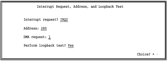
Select Yes for Perform loopback test?
The screen lists the installed adapter and shows the IRQ, address, and DMA settings assigned.
Press ENTER again to advance to the first screen of the loopback test.
Follow the instructions on the screen for each phase of the test. The software updates information on the screen during each test phase and then displays the test phase results.
The following screen displays for Phase 1:
Press any key to start the test.
The software performs the Basic Recognition Test, Hard Disk Conflict Test, and Register Test for Phase 1.
These instructions display for Phase 2:
Install the loopback test plug and press ENTER to start the test.
The software performs adapter Signal and Send/Receive tests for Phase 2.
When Phase 2 completes, these instructions display for Phase 3:
The software performs cable and modem Signal and Send/Receive tests for Phase 3.
Follow the instructions on the screen and then press ENTER to start the test.
If the loopback test fails, you need to know which phase failed. Watch the messages on the screen. TEST PASSED or TEST FAILED displays for each phase. At the end of the loopback test, a summary message displays.

A TEST PASSED message indicates all phases passed. A TEST FAILED message indicates one or more phases failed.
A failure in Phase 1 or 2 could indicate a problem with the adapter configuration. Check the following:
Is there an IRQ conflict with another adapter? If so, follow the instructions in section 17.1 to reset the IRQ.
Is the adapter address you specified in the software the same as the jumper settings on the adapter? If not, follow the instructions in section 17.1 to change the adapter address in the software.
Is there a DMA conflict with another adapter? If so, follow the instructions in section 17.1 to reset the DMA.
Is the adapter installed correctly? Make sure the adapter is firmly in the slot.
Is the adapter making a clean connection? Try cleaning the adapter slot connectors with a pencil eraser.
A failure in Phase 3 usually indicates a problem in the cable, modem, or both. Check for the following conditions:
Is the modem set to AL mode?
Is the modem cable connected correctly?
If any phase of the test fails, correct the problem reported by the phase that failed and repeat the test.