On the Communication Link tab you can specify the BARR/RJE communication protocol and physical attachment between the host system and remote computer. This topic describes the VTAM and NCP parameters you must specify in the BARR/RJE software for the communication link. These parameters must match those specified in the host VTAM and NCP parameter libraries. Your host programmer can provide the correct values to enter into the BARR/RJE software. VTAM is the mainframe program for the SNA communication protocol. NCP is the program that resides in the mainframe communications controllers.
When you finish configuring the communication links on the Communication Link tab, click NCP and Physical Unit to view sample statements the host programmer needs to enter in the host VTAM and NCP parameter libraries. The host programmer must set certain host parameters for BARR/RJE to operate. An existing remote definition used for other RJE equipment might not work with BARR/RJE. You will save time and effort getting your system running if you adhere to the recommended host definition. You can print these screens for the host programmer by clicking Print on the NCP or Physical Unit dialog box.
NCP definitions are available for 802.2 LLC2 and SDLC connections. Physical unit (VTAM) definitions are only available for 802.2 LLC2, HPR/IP, and SDLC switched connections.
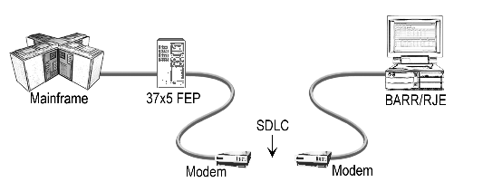
On SDLC switched (dial) lines, host modems automatically answer remote user phone calls as shown in the following graphic. The modems use the public phone system at speeds from 1,200 to 56,000 bps.

SDLC dial lines use modems to answer remote phone calls.
The BARR/SNA SDLC Link Service configuration utility and the SDLC Connection Configuration dialog box are used to configure the SDLC link service for the BARR/RJE software. The parameters specified are also used by VTAM and NCP on the mainframe. Your host programmer can provide you with the correct parameter values. After you enter the communication link parameters in the software, BARR/RJE produces samples of the statements the host programmer needs to enter in the host VTAM and NCP parameter libraries. You can view and print these statements by clicking NCP and Physical Unit on the Communication Link tab.
The following is the recommended NCP definition for an SDLC switched line. You can access this dialog box by clicking NCP on the Communication Link tab. The parameters that appear in the dialog box vary depending on the settings configured in the BARR/RJE software. The parameters that change are displayed in blue text.

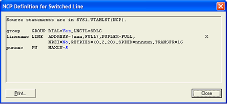
The GROUP macro instruction gives common parameter settings for all LINE macros in the group.
|
group |
GROUP DIAL=Yes,LNCTL=SDLC |
Required parameters
|
Parameter |
Description |
|
group |
Optional macro label. |
|
DIAL=Yes |
Indicates this is a dial-up line. |
|
LNCTL=SDLC |
Indicates the line control is SDLC. |
The LINE macro defines the line at the host and is necessary for SDLC connections.
|
linename LINE |
ADDRESS=(aaa,FULL),DUPLEX=FULL, |
X |
|
|
NRZI=Yes,RETRIES=(8,2,20),SPEED=nnnnnn,TRANSFR=16 |
|
|
Parameter |
Description |
|
linename |
The VTAM name of the communications line. |
|
ADDRESS= |
Line interface address. (aaa,FULL) – Indicates the line interface address, aaa, when you specify DATMODE=FULL. aaa – Indicates the line interface address, aaa, when you specify DATMODE=HALF. |
|
DUPLEX=FULL |
The line and modem can send and receive data simultaneously. |
|
NRZI=YES|NO |
NRZI is a method to encode binary data over a serial interface. Check if your host uses NRZI encoding. YES – Use NRZI encoding. Use this option if frequent SDLC aborts occur. NO – Do not use NRZI encoding. |
|
RETRIES=(m,t,n) |
The number of attempts the system will make to recover from communications errors. m – Maximum retransmissions of a frame while waiting for a normal response. The recommended value is 8. t – Time in seconds paused after m retransmissions have failed. The recommended value is 2. n – Number of times the above error recovery sequence is repeated. The recommended value is 20. |
|
SPEED=nnnnnn |
Required. Because the modem provides the bits-per-second clock, this parameter does not affect BARR/RJE functions, but the IBM Network Performance Monitor uses this value to calculate statistics. |
|
TRANSFR=16 |
The number of NCP buffers. This value corresponds to the maximum amount of data (the data transfer limit) that NCP will receive from the line during a single data transfer operation. |
System default values
|
Parameter |
Description |
|
CHECK=NODCD |
The Data Carrier Detect (DCD) line from the modem will not be monitored. |
|
CLOCKNG=EXT |
External clocking indicates that the modem’s clock will control the transmission rate. |
The PU macro names and describes a PU. At log on, the PU macro in the NCP definition is replaced with the PU macro from VTAM.
|
puname |
PU |
MAXLU=5 |
|
Parameter |
Description |
|
puname |
The PU’s name conforms to the naming convention at your site. The VTAM operator uses the name to vary the unit active or inactive and to query the unit’s status. |
|
MAXLU=n |
The maximum number of LUs used with this line. Use the LU macro formula to calculate the number of LUs you need. If you are upgrading from DOS-based BARR/RJE, the number of Non-RJE LUs specified on the Communication Link tab is also included in the calculation. |
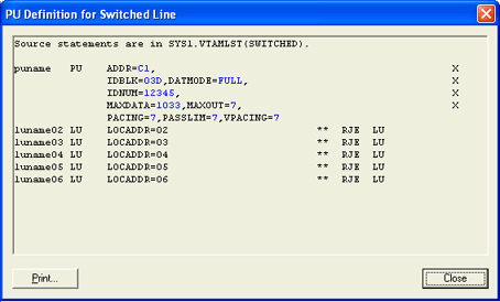
The PU macro names and describes a physical unit.
|
puname |
PU |
ADDR=C1, |
X |
|
|
|
IDBLK=03D,DATMODE=FULL, |
X |
|
|
|
IDNUM=12345, |
X |
|
|
|
MAXDATA=1033,MAXOUT=7, |
X |
|
|
|
PACING=7,PASSLIM=7,VPACING=7 |
|
|
Parameter |
Description |
|
puname |
The PU’s name conforms to the naming convention at your site. The VTAM operator uses the name to vary the unit active or inactive and to query the unit’s status. |
|
ADDR=C1 |
The 8-bit address used by SDLC. This address, the first byte of every frame, separates messages sent to different PUs on the same line. |
|
DATMODE=FULL|HALF |
Specify whether the PU data mode is full duplex or half duplex. FULL – Default. The system sends and receives data simultaneously resulting in twice the throughput. The V.32 modem standard supports full duplex on dial-up lines. Some modems do not support full-duplex communications. If you select DATMODE=FULL on the BARR/SNA SDLC Link Service Link tab, the host programmer must also specify it at the host. If the computer and host settings do not match, the software might have communication problems such as timeouts or lowered performance when it sends data to the host. HALF – In half duplex, the communications line is in either a send or receive mode so less than half the capacity of the line is available for use. To maximize performance, select DATMODE=FULL on the SDLC Connection Configuration dialog box and in the VTAM PU definition. You can achieve maximum BARR/RJE performance with full-duplex mode. Full duplex enables you to send and receive data simultaneously, often doubling throughput. You can even improve one-way throughput because you can receive acknowledgments while you send data. |
|
IDBLK=bbb |
Use these parameters to identify the remote’s PU definition. During Xid negotiation, the remote sends an Exchange ID that contains the IDBLK and IDNUM parameters. VTAM searches for the PU identified by IDBLK and IDNUM and uses this PU for the rest of the communications session. |
|
MAXDATA=265|521|1033|2057 |
The maximum amount of data you can send on the PU in one frame. This value includes nine bytes of header information plus the data length. The default value is 1033. To maximize performance, you can increase throughput by sending larger frames of data. Send 1024 bytes by setting MAXDATA to 1033 on the SDLC Connection Configuration dialog box and the VTAM PU definition. This step reduces the amount of control information and total number of frames sent. Setting MAXDATA to 2057 can result in greater system throughput, but it is not recommended for Ethernet or other LAN equipment that will not support the larger packet size. |
|
MAXOUT=7 |
Specifies that up to 7 frames of information will be sent before pausing for a response. The maximum MAXOUT value of 7 results in the highest throughput. |
|
PACING=n |
Determines how much data gets sent to BARR/RJE before the system needs a pacing response to send more data. Pacing is a flow-control mechanism that prevents the host from sending data faster than BARR/RJE can print or otherwise handle it. Values smaller than 7 often lower performance. This parameter overrides the SRCVPAC value in the LOGMODE. |
|
PASSLIM=n |
The maximum number of information frames sent to the PU at one time. This parameter is usually set to the same value as MAXOUT. |
|
VPACING=n |
Similar to the PACING parameter, but VPACING determines pacing between the RJE system and VTAM. Values less than 7 lower efficiency. To maximize performance, setting parameters to larger values can improve BARR/RJE performance. If PACING=7 and VPACING=7 in the VTAM PU definition, the host can send seven data frames before it requires a pacing response. On a half-duplex line, the host sends 7 frames at a time. When you specify PACING=7, the pacing response could be returned in time for 7 more frames of data to be sent. Include MAXOUT=7 in the PU definition. |
System default values
|
Parameter |
Description |
|
DISCNT=(NO) |
Do not disconnect the PU until BARR/RJE requests it. |
|
ISTATUS=ACTIVE |
The PU will be activated automatically. |
|
PUTYPE=2 |
BARR/RJE uses the Physical Unit Type 2 protocol. |
Other parameters
|
Parameter |
Description |
|
DLOGMOD=nnnnnnnn |
Specify the logon mode table entry to use by default. |
|
MODETAB=nnnnnnnn |
Specify the mode table containing the logmode entries. ISTINCLM is the default IBM-supplied mode table usually present with VTAM. |
|
SSCPFM=USSSCS |
If this parameter is set, then the host's logon type and the Logon type selected on the RJE Description tab, must be configured as Character Coded. The system default is SSCPFM=FSS, which indicates that the Logon type must be Formatted. |
The LU macro instructions define logical units allocated to the RJE devices.
|
luname02 LU |
LOCADDR=2, |
** RJE LU |
Use the LU macro formula to calculate the number of LUs you need.
Required parameters
|
Parameter |
Description |
|
lunamenn |
The LU name conforms to the naming convention at your site. BARR/RJE does not use this name. |
|
LOCADDR=i |
The local addresses must be unique. The maximum value for i is 20 when you use Barr software. MVS/JES2 supports a maximum of 13 LUs with BARR/RJE. |
|
BATCH=YES |
Indicates the processing priority. Batch applications, such as RJE, require low priority. While interactive applications, such as 3270 terminal sessions, usually have higher priority. For VTAM Version 4, Release 3 or later, replace this parameter with the Class of Service (COS) parameter in the LOGMODE for the host application. |
Dedicated point-to-point lines operate at speeds from 4,800 to 2,048,000 bps. You can lease dedicated lines from a phone company or install them in a single building or business. You can use either a modem or DSU/CSU, depending on whether the dedicated line is analog or digital.
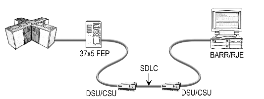
SDLC leased lines use modems or DSU/CSUs to answer remote phone calls.
The BARR/SNA SDLC Link Service configuration utility and the SDLC Connection Configuration dialog box are used to configure the SDLC link service for the BARR/RJE software. The parameters specified are also used by NCP on the mainframe. Your host programmer can provide you with the correct parameter values. After you enter the communication link parameters in the software, BARR/RJE produces a sample of the statement the host programmer needs to enter in the host NCP parameter library. You can view and print this statement by clicking NCP on the Communication Link tab.

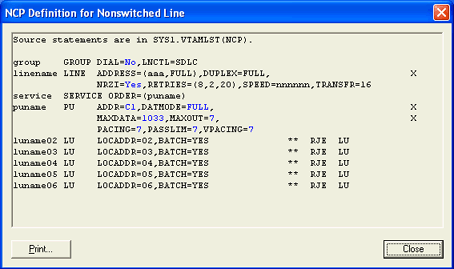
The GROUP macro instruction gives common parameter settings for all LINE macros in the group.
|
group |
GROUP DIAL=No,LNCTL=SDLC |
Required parameters
|
Parameter |
Description |
|
group |
Optional macro label. |
|
DIAL=NO |
Indicates a dedicated line. |
|
LNCTL=SDLC |
Indicates the line control is SDLC. |
The LINE macro defines the line at the host and is necessary for SDLC connections.
|
linename LINE |
ADDRESS=(aaa,FULL),DUPLEX=FULL, |
X |
|
|
NRZI=Yes,RETRIES=(8,2,20),SPEED=nnnnnn,TRANSFR=16 |
|
Required parameters
|
Parameter |
Description |
|
linename |
The VTAM name of the communications line. |
|
ADDRESS=(aaa,FULL) |
Indicates the line interface address, aaa, when you select DATMODE=FULL on the SDLC Connection Configuration dialog box and the VTAM PU definition. To maximize performance, when you set ADDRESS to FULL and there is only one address on the line (this is not a multidrop line), VTAM automatically keeps RTS high at all times. This setting also helps improve performance, especially on high-speed lines. |
|
DUPLEX=FULL |
The line and modem can send and receive data simultaneously. |
|
NRZI=YES|NO |
NRZI is a method to encode binary data over a serial interface. Check if your host uses NRZI encoding. YES – Use NRZI encoding. Use this option if frequent SDLC aborts occur. NO – Do not use NRZI encoding. |
|
RETRIES=(m,t,n) |
The number of attempts the system will make to recover from communications errors. m – Maximum retransmissions of a frame while waiting for a normal response. The recommended value is 8. t – Time in seconds paused after m retransmissions have failed. The recommended value is 2. n – Number of times the above error recovery sequence is repeated. The recommended value is 20. |
|
SPEED=nnnnnn |
Required. Because the modem provides the bits-per-second clock, this parameter has no effect on BARR/RJE functions. The IBM Network Performance Monitor uses this value to calculate statistics. |
|
TRANSFR=16 |
The number of NCP buffers. This value corresponds to the maximum amount of data (the data transfer limit) that NCP will receive from the line during a single data transfer operation. |
System default values
|
Parameter |
Description |
|
CHECK=NODCD |
The DCD line from the modem will not be monitored. |
|
CLOCKNG=EXT |
External clocking indicates that the modem’s clock controls the transmission rate. |
The SERVICE macro controls the order in which the PUs get serviced on a dedicated line.
|
service |
SERVICE ORDER=(puname) |
Required parameters
|
Parameter |
Description |
|
service |
The name of the SERVICE macro is arbitrary. You can have multiple SERVICE statements with the same name. |
|
ORDER=(puname) |
The operands in the ORDER list give the order in which the PUs will be polled on a multipoint line. You can preferentially service one of the PUs on a multipoint line by listing it more than once in the ORDER list. |
The PU macro names and describes a PU. You can operate several PUs on the same line (multipoint). Each unit requires a separate PU macro instruction.
|
puname PU |
ADDR=C1,DATMODE=FULL, |
X |
|
|
MAXDATA=1033,MAXOUT=7, |
X |
|
|
PACING=7,PASSLIM=7,VPACING=7 |
|
Required parameters
|
Parameter |
Description |
|
puname |
The PU’s name conforms to the naming convention at your site. The VTAM operator uses the name to vary the unit active or inactive and to query the unit’s status. |
|
ADDR=aa |
The 8-bit address used by SDLC. This address, the first byte of every frame, separates messages sent to different PUs on the same line. |
|
DATMODE=FULL|HALF |
Specify whether the PU data mode is full or half duplex. FULL – Default. The system sends and receives data simultaneously resulting in up to twice the normal throughput. The V.32 modem standard supports full duplex on dial-up lines. Some modems do not support full-duplex communications. If you select DATMODE=FULL on the SDLC Connection Configuration dialog box, the host programmer must also specify it at the host. If the computer and host settings do not match, the software might have communication problems such as timeouts or lowered performance when it sends data to the host. HALF – In half duplex, the communications line is either in a send or receive mode, so less than half the capacity of the line is available for use. To maximize performance, specify DATMODE=FULL on the SDLC Connection Configuration dialog box and the VTAM PU definition. You can achieve maximum BARR/RJE performance with full-duplex mode. Full duplex enables you to send and receive data simultaneously, often doubling throughput. You can even improve one-way throughput because you can receive acknowledgments while you send data. |
|
MAXDATA=265|521|1033|2057 |
The maximum amount of data you can send on the PU in one frame. This value includes nine bytes of header information plus the data length. The default value is 1033. To maximize performance, you can increase throughput by sending larger frames of data. Send 1024 bytes by setting MAXDATA to 1033 on the SDLC Connection Configuration dialog box and the VTAM PU definition. This step reduces the amount of control information and total number of frames sent. A MAXDATA value of 2057 can result in greater system throughput, but it is not recommended for Ethernet or other LAN equipment that will not support the larger packet size. |
|
MAXOUT=n |
Specifies that up to n frames of information can be sent before waiting for a response. The maximum MAXOUT value of 7 will result in the highest throughput. |
|
PACING=n |
Determines how much data to send to BARR/RJE before a pacing response is needed to send more data. Pacing is a flow-control mechanism that prevents the host from sending data faster than BARR/RJE can print or otherwise handle it. Values smaller than the MAXOUT parameter often lower performance. |
|
PASSLIM=n |
The maximum number of information frames sent to the PU at one time, which is usually set to the same value as MAXOUT. |
|
VPACING=n |
Similar to the PACING parameter, but VPACING determines pacing between the RJE system and VTAM. VPACING is usually set to the same value as MAXOUT. To maximize performance, setting parameters to larger values can improve BARR/RJE performance. With PACING=7 and VPACING=7 in the VTAM PU definition, the host can send 7 data frames before it requires a pacing response. On a half-duplex line, the host sends 7 frames at a time. When you use PACING=7, the pacing response could be returned in time for you to send 7 more frames of data. Include MAXOUT=7 in the PU definition. |
System default values
|
Parameter |
Description |
|
DISCNT=(NO) |
Do not disconnect the PU until BARR/RJE requests it. |
|
ISTATUS=ACTIVE |
The PU will be activated automatically. |
|
PUTYPE=2 |
BARR/RJE uses the PU Type 2 protocol. |
Other useful parameters
|
Parameter |
Description |
|
DLOGMOD=nnnnnnnn |
Specify the logon mode table entry to use by default. |
|
MODETAB=nnnnnnnn |
Specify the mode table containing the logmode entries. ISTINCLM is the default IBM-supplied mode table usually present with VTAM. |
|
SSCPFM=USSSCS |
If this parameter is set, then the host's logon type and the Logon type selected on the RJE Description tab, must be configured as Character Coded. The system default is SSCPFM=FSS, which indicates that the Logon type must be Formatted. |
The LU macro instruction defines LUs allocated to the RJE devices.
|
luname02 LU |
LOCADDR=2,BATCH=YES |
** RJE LU |
Use the LU macro formula to calculate the number of LUs you need.
Required parameters
|
Parameter |
Description |
|
lunamenn |
The LU name conforms to the naming convention at your site. BARR/RJE does not use this name. |
|
LOCADDR=i |
The local addresses must be unique. The maximum value for i is 20 when you use Barr software. MVS/JES2 supports a maximum of 13 LUs. |
|
BATCH=YES |
Indicates the processing priority. Batch applications, such as RJE, require low priority. While interactive applications, such as 3270, usually have higher priority. For VTAM Version 4, Release 3 or later, this parameter is replaced by the Class of Service (COS) parameter in the LOGMODE for the host application. |
As shown in the following graphic, the 3725 and 3745 front-end processors (FEPs) attach to an 802.2 network through a TIC.
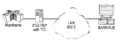
FEPs attach to an 802.2 network through TICs.
The BARR/SNA 802.2 Link Service configuration utility and the 802.2 Connection Configuration dialog box are used to configure the 802.2 LLC2 link service for the BARR/RJE software. The parameters specified are also used by VTAM and NCP on the mainframe. Your host programmer can provide you with the correct parameter values. After you enter the communication link parameters in the software, BARR/RJE produces samples of the statements the host programmer needs to enter in the host VTAM and NCP parameter libraries. You can view and print these statements by clicking NCP and Physical Unit on the Communication Link tab.

The following is the recommended NCP definition for an 802.2 LLC2 connection. You can access this dialog box by clicking NCP on the Communication Link tab. The parameters that appear in the dialog box vary depending on the settings configured in the BARR/RJE software. The parameters that change are displayed in blue text.

The GROUP macro instruction for the physical group includes common parameter settings for all LINE macros in the group.
|
group |
GROUP ECLTYPE=PHYSICAL |
Required parameters
|
Parameter |
Description |
|
group |
Optional macro label. |
|
ECLTYPE=PHYSICAL |
This GROUP macro defines a physical connection to the 802.2 LLC2. |
The LINE macro defines the line at the host.
|
linename LINE |
ADDRESS=(aaaa,FULL),LOCADD=400000000001, |
X |
|
|
PORTADD=pp,RCVBUFC=4095 |
|
Required parameters
|
Parameter |
Description |
|
linename |
The VTAM name of the communications line. |
|
ADDRESS=(aaaa,FULL) |
Specifies the logical address for the network card in the NCP where aaaa is the address. |
|
LOCADD=4000abbbbbbb |
The locally administered address for the network card for the host where a is a digit from 0 to 7 and b is a hexadecimal digit from 0 to F. |
|
PORTADD=pp |
The port number pp that associates a physical line with a logical line. The number must be the same as the PHYPORT parameter on the logical line. |
|
RCVBUFC=4095 |
This parameter sets the maximum amount of data the host can receive from the 802.2 LLC2 link. |
The GROUP macro for the logical group defines a logical connection to the 802.2 network.
|
group |
GROUP ECLTYPE=LOGICAL,AUTOGEN=100, |
X |
|
|
CALL=INOUT,PHYPORT=pp |
|
Required parameters
|
Parameter |
Description |
|
group |
Optional macro label. |
|
ECLTYPE=LOGICAL |
This GROUP macro defines a logical connection to the 802.2 LLC2. |
|
AUTOGEN=100 |
The number of lines and groups supported by NCP. |
|
CALL=INOUT |
Both VTAM and BARR/RJE can initiate the connection. |
|
PHYPORT=pp |
The port number pp that associates a physical line with a logical line. The number must be the same as the PORTADD parameter on the physical line. |
The PU macro names and describes a physical unit. The PU macro in the NCP definition is replaced at log on with the PU macro from VTAM.
|
puname |
PU |
MAXLU=5 |
Required parameters
|
Parameter |
Description |
|
puname |
The PU’s name conforms to the naming convention at your site. The VTAM operator uses the name to vary the unit active or inactive and to query the unit’s status. |
|
MAXLU=n |
The maximum number of LUs to use with this line. Use the LU macro formula to calculate the number of LUs you need. If you are upgrading from DOS-based BARR/RJE, the number of Non-RJE LUs specified on the Communication Link tab is also included in the calculation. |
The following is the recommended PU definition for an 802.2 LLC2 connection. You can access this dialog box by clicking Physical Unit on the Communication Link tab. The parameters that appear in the dialog box vary depending on the settings configured in the BARR/RJE software. The parameters that change are displayed in blue text.
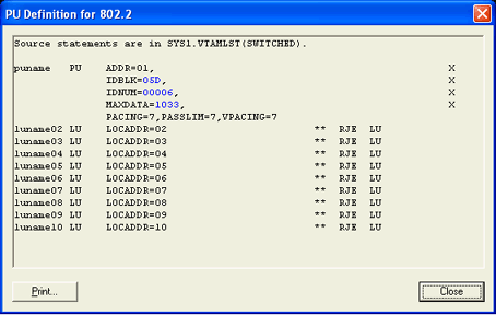
The PU macro names and describes a physical unit.
|
puname PU |
ADDR=01, |
X |
|
|
IDBLK=03D, |
X |
|
|
IDNUM=12345, |
X |
|
|
MAXDATA=1033, |
X |
|
|
PACING=7,PASSLIM=7,VPACING=7 |
|
Required parameters
|
Parameter |
Description |
|
puname |
The PU’s name conforms to the naming convention at your site. The VTAM operator uses the name to vary the unit active or inactive and to query the unit’s status. |
|
ADDR=01 |
Required. |
|
IDBLK=bbb |
Parameters used on an 802.2 network to identify the remote’s PU definition. During Xid negotiation, the remote sends an Exchange ID that contains the IDBLK and IDNUM parameters. VTAM searches for the PU identified by IDBLK and IDNUM and uses this PU for the rest of the communications session. |
|
MAXDATA=265|521|1033|2057 |
The maximum amount of data you can send on the PU in one frame. This count includes nine bytes of header information plus the data length. The default value is 1033. To maximize performance, you can increase throughput by sending larger frames of data and thus reduce the amount of control information and total number of frames sent. Send 1024 bytes by setting MAXDATA to 1033 on the 802.2 Connection Configuration dialog box and VTAM PU definition. Setting MAXDATA to 2057 can result in greater system throughput, but it is not recommended for Ethernet or other LAN equipment that will not support the larger packet size. |
|
PACING=n |
Determines how much data the host sends to BARR/RJE before it needs a pacing response to send more data. Pacing is a flow-control mechanism that prevents the host from sending data faster than BARR/RJE can print or otherwise handle it. Values smaller than 7 often lower performance. |
|
PASSLIM=n |
The maximum number of information frames sent to the PU at one time. |
|
VPACING=n |
Similar to the PACING parameter, but VPACING determines pacing between the RJE system and VTAM. Values less than 7 lower efficiency. To maximize performance, setting parameters to larger values can improve BARR/RJE performance. With PACING=7 and VPACING=7 in the VTAM PU definition, the host can send 7 data frames before it requires a pacing response. On a half-duplex line, it sends 7 frames at a time. When you use PACING=7, the pacing response could be returned in time to send 7 more frames of data. |
System default values
|
Parameter |
Description |
|
DISCNT=(NO,F) |
Does not disconnect the PU until requested by BARR/RJE. |
|
ISTATUS=ACTIVE |
Automatically activates the PU. |
|
PUTYPE=2 |
BARR/RJE uses the Physical Unit Type 2 protocol. |
Other useful parameters
|
Parameter |
Description |
|
DLOGMOD=nnnnnnnn |
Names the logon mode table entry to use by default. |
|
MODETAB=nnnnnnnn |
Specifies the mode table containing the logmode entries. ISTINCLM is the default IBM-supplied mode table usually present with VTAM. |
|
SSCPFM=USSSCS |
If this parameter is set, then the host's logon type and the Logon type selected on the RJE Description tab, must be configured as Character Coded. The system default is SSCPFM=FSS, which indicates that the Logon type must be Formatted. |
The LU macro instructions define LUs allocated to the RJE devices.
|
luname02 LU |
LOCADDR=2, |
** RJE LU |
|
luname03 LU |
LOCADDR=3, |
** RJE LU |
|
luname04 LU |
LOCADDR=4, |
** RJE LU |
|
luname05 LU |
LOCADDR=5, |
** RJE LU |
|
luname06 LU |
LOCADDR=6, |
** RJE LU |
Use the LU macro formula to calculate the number of LUs you need.
Required parameters
|
Parameter |
Description |
|
lunamenn |
The LU name conforms to the naming convention at your site. BARR/RJE does not use this name. |
|
LOCADDR=i |
The local addresses must be unique. The maximum value for i is 20 when you use Barr software. MVS/JES2 supports a maximum of 13 LUs with BARR/RJE. |
As shown in the following graphic, HPR/IP uses any interface network card, such as Ethernet One of the LAN physical standards. It allows multiple stations to access the transmission medium. to connect to the mainframe.
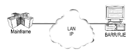
HPR/IP connections connect to the mainframe using IP.
The BARR/SNA HPR/IP Link Service configuration utility and the HPR/IP Connection Configuration dialog box are used to configure the HPR/IP link service for the BARR/RJE software. The parameters specified are also used by VTAM on the mainframe. Your host programmer can provide you with the correct parameter values. After you enter the communication link parameters in the software, BARR/RJE produces a sample of the statements the host programmer needs to enter in the host VTAM parameter library. You can view and print these statements by clicking Physical Unit on the Communication Link tab.

For HPR/IP connections, you must perform additional TCP/IP and VTAM configuration.
The following is the recommended PU definition for an HPR/IP connection. You can access this dialog box by clicking Physical Unit on the Communication Link tab. The parameters that appear in the dialog box vary depending on the settings configured in the BARR/RJE software. The parameters that change are displayed in blue text.

The PU macro names and describes a physical unit.
|
puname PU |
ADDR=01, |
X |
|
|
IDBLK=03D, |
X |
|
|
IDNUM=12345, |
X |
|
|
MAXDATA=1033, |
X |
|
|
PACING=7,PASSLIM=7,VPACING=7 |
|
Required parameters
|
Parameter |
Description |
|
puname |
The PU’s name conforms to the naming convention at your site. The VTAM operator uses the name to vary the unit active or inactive and to query the unit’s status. |
|
ADDR=01 |
Required. |
|
IDBLK=bbb |
Parameters used on an IP network to identify the remote’s PU definition. During Xid negotiation, the remote sends an Exchange ID that contains the IDBLK and IDNUM parameters. VTAM searches for the PU identified by IDBLK and IDNUM and uses this PU for the rest of the communications session. |
|
MAXDATA=265|521|1033|2057 |
The maximum amount of data you can send on the PU in one frame. This count includes nine bytes of header information plus the data length. The default value is 1033. To maximize performance, you can increase throughput by sending larger frames of data and thus reduce the amount of control information and total number of frames sent. Send 1024 bytes by setting MAXDATA to 1033 on the HPR/IP Connection Configuration dialog box and VTAM PU definition. Setting MAXDATA to 2057 can result in greater system throughput, but it is not recommended for Ethernet or other LAN equipment that will not support the larger packet size. |
|
PACING=n |
Determines how much data the host sends to BARR/RJE before it needs a pacing response to send more data. Pacing is a flow-control mechanism that prevents the host from sending data faster than BARR/RJE can print or otherwise handle it. Values smaller than 7 often lower performance. |
|
PASSLIM=n |
The maximum number of information frames sent to the PU at one time. |
|
VPACING=n |
Similar to the PACING parameter, but VPACING determines pacing between the RJE system and VTAM. Values less than 7 lower efficiency. To maximize performance, setting parameters to larger values can improve BARR/RJE performance. With PACING=7 and VPACING=7 in the VTAM PU definition, the host can send 7 data frames before it requires a pacing response. On a half-duplex line, it sends 7 frames at a time. When you use PACING=7, the pacing response could be returned in time to send 7 more frames of data. |
System default values
|
Parameter |
Description |
|
DISCNT=(NO,F) |
Does not disconnect the PU until requested by BARR/RJE. |
|
ISTATUS=ACTIVE |
Automatically activates the PU. |
|
PUTYPE=2 |
BARR/RJE uses the Physical Unit Type 2 protocol. |
Other useful parameters
|
Parameter |
Description |
|
DLOGMOD=nnnnnnnn |
Names the logon mode table entry to use by default. |
|
MODETAB=nnnnnnnn |
Specifies the mode table containing the logmode entries. ISTINCLM is the default IBM-supplied mode table usually present with VTAM. |
|
SSCPFM=USSSCS |
If this parameter is set, then the host's logon type and the Logon type selected on the RJE Description tab, must be configured as Character Coded. The system default is SSCPFM=FSS, which indicates that the Logon type must be Formatted. |
The LU macro instructions define LUs allocated to the RJE devices.
|
luname02 LU |
LOCADDR=2, |
** RJE LU |
|
luname03 LU |
LOCADDR=3, |
** RJE LU |
|
luname04 LU |
LOCADDR=4, |
** RJE LU |
|
luname05 LU |
LOCADDR=5, |
** RJE LU |
|
luname06 LU |
LOCADDR=6, |
** RJE LU |
Use the LU macro formula to calculate the number of LUs you need.
Required parameters
|
Parameter |
Description |
|
lunamenn |
The LU name conforms to the naming convention at your site. BARR/RJE does not use this name. |
|
LOCADDR=i |
The local addresses must be unique. The maximum value for i is 20 when you use Barr software. MVS/JES2 supports a maximum of 13 LUs with BARR/RJE. |