 If you use print spooling or a LAN connection and you define
the corresponding directory on your local PC drive, execute the DOS share
command to load file-sharing support before you start BARR/RJE.
If you use print spooling or a LAN connection and you define
the corresponding directory on your local PC drive, execute the DOS share
command to load file-sharing support before you start BARR/RJE.After you install and configure the BARR/RJE software, you can start BARR/RJE. At startup, BARR/RJE first connects with and then logs on to the host. The BARR/RJE Operation screen allows you to monitor the connection and logon process. You must complete this startup process each time you use BARR/RJE.
You can start BARR/RJE one of these ways:
From the BARR/RJE Installation Description screen
From the DOS prompt
When you power on the PC
With different configuration files (for different host sites)
From an application program
The examples in this section illustrate these methods. Chapter 26 describes how to call BARR/RJE from an application program.
 If you use print spooling or a LAN connection and you define
the corresponding directory on your local PC drive, execute the DOS share
command to load file-sharing support before you start BARR/RJE.
 If keystrokes cause communications errors (as described in
Chapter 22), use the TSR
command bios_key
to eliminate the problem before you start BARR/RJE.
Starting BARR/RJE from the Installation Description screen allows you to change the software configuration.
If you are not already on the Installation Description screen, enter the following command at the DOS prompt:
barrsnar i
Change your BARR/RJE configuration as needed. Chapter 6 describes how to change your BARR/RJE configuration.
Exit the Installation screens and save your changes. From the Installation Description screen, select Exit and Save Changes.
To run BARR/RJE, select Begin Communications at Operation screen from the Exit Options screen.
Starting BARR/RJE from the DOS prompt uses the existing configuration.
 From a DOS prompt, enter the following command:
barrsnar
Starting BARR/RJE when you power on the PC uses the existing configuration.
 Add the startup command C:\BARR\BARRSNAR to your AUTOEXEC.BAT
file. This file contains the commands to execute when you power on (or
boot up) the PC.
Different mainframe computers require different BARR/RJE configurations. When you start BARR/RJE, you can specify a configuration file that contains configuration parameters for a specific mainframe.
Create additional configuration files. Chapter 19 describes how to create configuration files.
Run BARR/RJE from the DOS prompt with a parameter to specify a configuration file as follows:
barrsnar @filename
For example, to run BARR/RJE with the configuration file RJE.CFG, enter this command:
barrsnar @rje.cfg
When you start BARR/RJE, you begin communications at the Operation screen. The Operation screen reflects the activity taking place while BARR/RJE tries to connect with and log on to the mainframe.

The Operation screen is divided into four parts:
The Communication Scope monitors the link to the mainframe.
The Status Line displays the status of printers and other PC devices.
The Console displays both diagnostic and status messages.
The Command menu lists available commands.
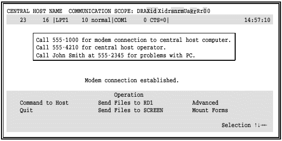
Your host name and the words Communication Scope appear on the top line of the Operation screen. The Communication Scope displays communication activity between your PC and the host. Chapter 23 describes the Communication Scope.
The second line on the Operation screen is the Status Line. It displays the status of devices and the time of day. Device status information includes the number of lines received and sent, parallel printer status, and serial printer status. A vertical line separates the device fields.
23 16
23 Number of lines received.
16 Number of lines sent.
 SDLC Connections: DSR=0
appears instead of the line status until BARR/RJE connects to the mainframe.
LPT1 10 normal
LPT1 Printer for which information is displayed; that is, LPT1, LPT2, or LPT3.
10 Line in the file the printer is currently printing.
normal Current status of the printer as follows:
normal Printer is functional.
busy Printer is too busy to accept any input.
off Printer is offline or the power is off.
error Printer is in an error state.
paper Printer is out of paper or the cable is not connected.
Parallel printer status is more precisely defined by the electrical signals on the printer cable. Table 20-1 lists electrical signals that correspond to the printer status.
Table 20-1. Printer Status Electrical Signals
|
Status |
Electrical Signals |
||
|
Busy |
/Error |
PE (Paper Error) | |
|
Pin 11 |
Pin 15 |
Pin 12 | |
|
off |
0V |
0V |
0V |
|
off |
0V |
0V |
+5V |
|
normal |
0V |
+5V |
0V |
|
normal |
0V |
+5V |
+5V |
|
error |
+5V |
0V |
0V |
|
paper |
+5V |
0V |
+5V |
|
busy |
+5V |
+5V |
0V |
|
busy |
+5V |
+5V |
+5V |
COM1 0 CTS=0
COM1 Serial printer for which information is displayed; that is, COM1, COM2, COM3, or COM4.
0 Line in the file the printer is currently printing.
CTS=0 Current status of the printer as follows:
normal Printer is functional.
CTS=0 Clear-To-Send signal is off. No data will be sent to this device.
DSR=0 Data-Set-Ready signal is off. No data will be sent to this device.
XOFF XOFF flow control character has been received. No data will be sent to this device. Receipt of XON flow control character will clear this condition.
The console appears on lines 3 through 20 of the Operation screen. The console displays dial-up call progress, the mainframe session status, and diagnostic messages. You can save a log file of console messages to disk. See Chapter 10 for more information.
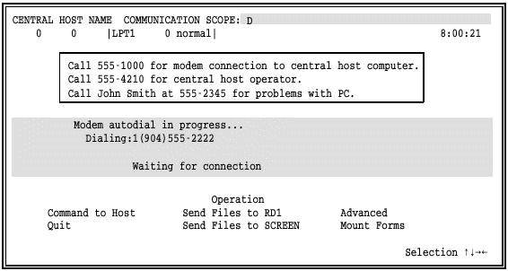
Initially the console displays the Startup Screen Notes you entered in the BARR/RJE configuration. The name and phone numbers in the screen example below get replaced by the name and phone numbers of your contacts. Chapter 16 describes Startup Screen Notes.
The next message on the console is the startup message. It displays in the center of the console and notifies you about connection progress. The specific text of the startup message varies, depending on your connection type. Different messages display for a PC-SYNC or AT autodial modem, a dedicated line, an external modem with manual dialing, and an external modem with dialing via the modems internal settings.
A message in the center of the screen notifies you that the modem is dialing.

The Communication Scope reports call progress. Special scope characters, called dial-up scope characters, indicate the activity taking place.
Dial-up scope characters (see Table 20-2) display in white and show the activity taking place. For instance, you can see if the phone number was dialed, if there was no answer, or if the line was busy.
Table 20-2. Dial-Up Scope Characters
|
Character |
Description |
|
A |
Answer tone. Host modem sent answer tone to remote. |
|
B |
Busy. Host modem is busy. |
|
D |
Dialing. In the process of dialing. |
|
N |
No answer tone. No answer tone has been detected. Modem will redial. |
|
R |
Ringing. Host modem is ringing. |
Dial-up scope characters usually appear in combinations on your Communication Scope as in the following examples:
DB Dialing/Busy.
DRA Dialing/Ringing/Answer tone.
DRND Dialing/Ringing/No answer tone/Redialing.
If your PC connects via a dedicated line or network connection, startup is automatic. The following screen indicates startup is complete.

If you use an external modem and need to manually dial the phone number, follow these steps:
Turn on the modem.
Press the Talk button or set the switch to Talk.
Dial the host computers phone number.
Wait for the computer to answer.
Listen for the high-pitched data tone.
Press the Data or Normal button or set the switch to Data or Normal.
Place the telephone receiver in the communications cradle or set the receiver aside until you disconnect it.
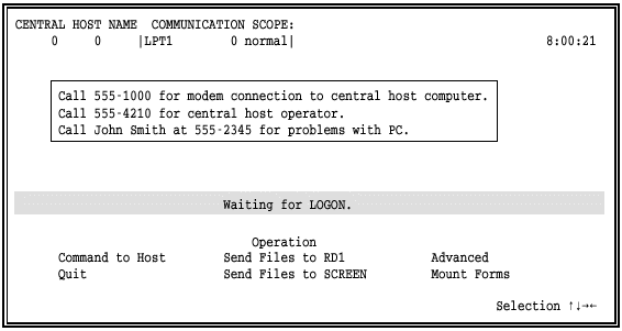
After you connect, the Waiting for Logon message displays.

If you use an external modem and dial the phone number with the modems internal settings, the Waiting for Logon message displays while BARR/RJE waits for the modem to make a connection.

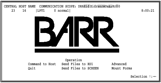
The word BARR in big block letters indicates that BARR/RJE successfully logged on to the mainframe computer. You can then monitor the status of your communications session with the Communication Scope. Chapter 22 provides more information about the Communication Scope.

When BARR/RJE tries to log on to the mainframe, error messages display on the console. If you receive an error message instead of a logon message, review the following common errors and resolutions.
In this example, the LOGMODE is incorrect.

In this example, the remote name or password is incorrect.

In this example, the number of LUs is incorrect. The VTAM PU definition specifies more LUs than the NCP MAXLU parameter.

In this example, the reader device is not started. The reader device was drained or not defined in JES2.
