
From the Devices and Printers menu, you select the types of printers and other PC or LAN devices to use with BARR/RJE. The devices you enable on this menu display on the Assign Devices screen.
This chapter introduces you to the concepts of source and destination devices and describes the devices you can enable from the Devices and Printers menu.
To define devices in the Barr software, you must understand the concepts of source devices, destination devices, and device assignment.
Devices that input data to the software are called data sources. RJE printers and punches are data sources because data travels from the RJE print or punch stream into the PC and is processed by the software. Devices that handle data output by the software are known as data destinations. PC printers and disk files are destinations because data on the PC is sent out to the printer or to a file on the hard disk. Figure 8-1 illustrates the PC data flow.
Routing data from a source to a destination is called assigning devices. For instance, files received from the RJE print stream can be directed or assigned to write to a printer attached to the PC parallel port.

Figure 8-1. Devices used with Barr software are either data sources or data destinations. Data travels from sources to the Barr PC and from the Barr PC to destinations.
After you define source and destination devices from the Devices and Printers menu, you can make device assignments on the Assign Devices screen described in Chapter 10.
The Devices and Printers menu lists standard PC devices as well as some devices that are unique to the Barr software.
Devices used with any print option software you purchased are not included on this menu. They display as separate items on the Installation Description menu. (Available print options include PRINT370, PRINT/TWINAX, BARR/PRINT for LAT, and BARR/PRINT for TCP/IP.)
 To reach the Devices and Printers menu, select Devices and Printers:
LPT, COM, NET, SEND, LAN from the Installation Description
menu.
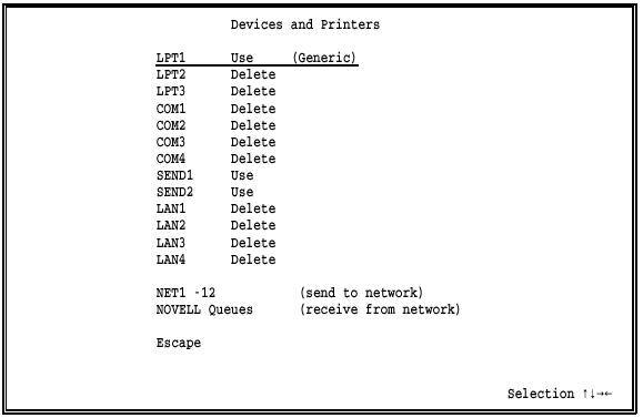
This section briefly describes the devices on this menu. Each device is described in detail in a separate section later in this chapter.
LPT1-LPT3
Parallel printers are attached to the PC parallel ports. LPT1, LPT2, and LPT3 are the DOS names for these ports. LPT1 is enabled by default. See section 8.3 for instructions to set up these devices.
 Performance Tuning: For BARR/RJE, it is more efficient
to print to parallel ports than to serial ports.
COM1-COM4
Serial printers and other serial devices are attached to the PC serial ports. COM1, COM2, COM3, and COM4 are the DOS names for these ports. BARR/RJE supports both input and output on the serial ports.
COM3 and COM4 are supported only on standard PC (ISA) bus machines. They require COM3 and COM4 adapters that can be set to interrupt levels other than IRQ4 and IRQ3, so that the four serial ports use four different interrupt levels. (Usually COM1 and COM3 use IRQ4 and COM2 and COM4 use IRQ3. However, the ISA bus does not allow interrupt sharing, which means you cannot use all four ports simultaneously with interrupts when IRQ4 and IRQ3 are the only choices.)
See section 8.4 for instructions to set up these devices.
 Performance Tuning: If you do not use the serial devices,
disable them. This frees buffers and makes them available to other program
features.
SEND1-SEND2
The SEND devices specify destinations for the Barr Send Files command. Usually SEND devices are used to direct files to the mainframe. You can issue the Send Files command from the Operation screen if you enable at least one SEND device. Both SEND1 and SEND2 are enabled by default. See section 8.9 for more information about these devices.
LAN1-LAN4
LAN connection devices automatically move files from a directory on a local area network to another location. You can direct files to another LAN location, to the mainframe, or to a printer from four different LAN directories. This option allows users on the network to share the RJE features of a single PC by simply copying files to the designated directory. See section 8.10 for instructions to set up these devices.
NET1-12 (send to network)
NET devices send data from the PC to printers on the local area network. Most networks support redirection of LPT1 to LPT3 with device drivers, but some networks support redirection of LPT1 to LPT12. On Novell networks, you can send files to NetWare print queues. On TCP/IP networks, you can send files to LPR or UNIX print queues. You can also send files to device drivers. See section 8.5 for instructions to set up these devices.
NOVELL Queues (receive from network)
Data can be received to the PC from Novell NetWare job queues or print queues. You can use up to four Novell queues and direct the received data to PC printers or route it to the mainframe as a job. See section 8.11 for instructions to set up these devices.
When you attach devices to the PC parallel ports, you need to set the options described in this section.
After you configure your printer, you can print a test file to verify that the configuration is correct. See Appendix D, Printer Test, for instructions to perform this test.
 From the Devices and Printers menu, select an LPT device.
For example, select LPT1.
A list of options displays.
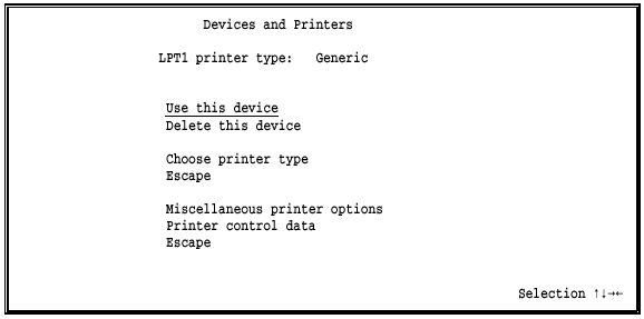
The same choices display for each LPT device.
Use this device
Enable the LPT device. You must select this option to enable the device before you can use it. The selected LPT device displays as a destination device on the Assign Devices screen. LPT1 is enabled by default.
Delete this device
Disable the LPT device and remove it from the Assign Devices screen. The status (deleted) displays next to the device name at the top of the screen. The Assign Devices screen is easier to read if you disable devices you do not intend to use.
Choose printer type
You must choose the type of printer to use. When you select this option, a list of printers displays. Section 8.6 describes the printer choices. After you make a selection, your choice displays on the Devices and Printers menu next to the device name. On the sample screen above, the printer type is Generic.
Miscellaneous printer options
Several options affect printer performance. For a description of these options, see Miscellaneous Printer Options for LPT Devices later in this section.
For a description of other options that affect printing, see section 18.2, Tuning and Global Options, Printer Control.
Printer control data
Printer control data allows you to send control codes to the printer, such as commands to set the lines-per-form and lines-per-inch or commands to reset the printer. You can use printer control data alone or with Barr printer forms. Section 8.8 tells you how to set up this feature.
Escape
The Escape option appears twice on the screen. Select Escape or press the ESC key to return to the Devices and Printers menu.
You can use several printer options with LPT devices to simplify print data processing or to solve printing problems.
 From the Devices and Printers menu for the selected LPT
device, select Miscellaneous
printer options.
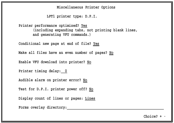
This screen shows the options you would see if you selected D.P.I. as the printer type.
Printer performance optimized?
Choose whether BARR/RJE should optimize printer performance by converting data as it is sent to the printer.
Yes Default. Printer performance is improved by changing the data as follows:
Blank lines are converted to line feeds (LF).
If the printer has Direct Access Vertical Forms Unit (DAVFU) support, the hardware skip-to-VFU channel commands are used to perform high-speed skipping of blank lines. DAVFU is a Dataproducts convention for specifying vertical forms control.
Horizontal tab characters are converted to the required number of blanks to emulate tab settings at eight-character intervals.
No Data is not changed when it is sent to the printer.
Conditional new page at end of file?
Choose whether the software should add a form feed (FF) to the end of a file, if needed. This option ensures that each file begins at the top of a new page, which is helpful when form feeds are missing from some files.
Yes Default. At the end of each file, the software determines whether a form feed is included or whether the maximum page length is reached. One of these conditions is necessary to ensure that the next file begins at the top of a new page. If neither condition is met, the software adds a form feed. The software remembers if it adds a form feed, and if the next file contains a form feed at the beginning, the software removes it to prevent printing a blank page.
No Form feeds are not added to or removed from files.
Make all files have an even number of pages?
Choose whether all files should have an even number of pages for easier job separation.
No Default. The number of printed pages can be even or odd.
Yes If a file has an odd number of pages, add a blank page to make the number of pages even. This ensures that the job banner page always faces up on the fan-fold paper stack.
Enable VFU download into printer?
This option displays only if you select a printer that supports Vertical Forms Unit (VFU) download on the Choose Printer Type screen. Printers that support VFU include Dataproducts, D.P.I., Genicom Linewriter, Printronix, Sand, Fujitsu, Hitachi, or STC (D.P.I.). For a complete list of the printers with VFU capability, see Lines-per-form and Lines-per-inch in section 8.6.
No Default. Do not use VFU to control line skips. This choice might be necessary with forms that do not have a 1 in the first position of the VFU. To print extended ASCII codes, such as the cent symbol (’), you must set this option to No.
Yes Use VFU to control line skips. The Dataproducts BP1500 requires a 1 in the first position of the VFU. You also should set Printer performance optimized to Yes.
Printer timing delay:
Some line printers cannot accept data as quickly as the software can send it. You can use this option to slow the rate at which data is sent to the printer, so the printer does not become backed up. Indications that you need to adjust this value include dropped or duplicate characters in the print output. You also might need to use this option with forms that do not have a 1 in the first position of the VFU.
 The timing delay feature applies only to line printers, not
to laser printers.
Line printers use a busy line to signal whether they can receive data. When a printer is busy it sets the busy line. Before the software sends data to the printer, it checks whether the busy line is set. If the busy line is active, the software pauses before sending more data. However, some printers are slow to set the busy line. The Printer timing delay option introduces a delay after each byte sent to the printer so the printer has time to set the busy line before the software sends more data.
Because the timing delay is measured in internal program cycles, the length of the delay depends on your PCs processor speed. The amount of the delay required also depends on your line printer.
The default value of 8 applies to PC AT workstations and most line printers. For a BARR/DPI printer adapter, set the timing delay value to 0. (The BARR/DPI adapter supports printers with the Dataproducts interface.) The maximum value is 9999 cycles.
If you need to change the timing delay, adjust it on a trial-and-error basis. First, set the timing delay to a large value such as 300 and note how the new value affects the printer. If the value is too high, the print speed will be noticeably slower. If the value is too low, the original problem will still be evident. Adjust the value up or down in smaller increments until the problem is resolved and the print speed seems normal.
For a description of the busy line, see the IBM Technical Reference, Options and Adapters, Volume 1, Graphics Printer section. Over-driving the printer is impossible if you use the IBM definition. Unfortunately, not all printers use this definition. Barr Systems Technical Support can help you tune this option.
Audible alarm on printer error?
Choose whether the PC will make a shrill beep when an error or paper condition occurs. The noise will stop when you correct the condition or press a key on the keyboard.
No Default. Disable the error alarm.
Yes Enable the error alarm. When error or paper displays on the Status Line, a beep will sound. This choice is especially useful for laser printers. Unlike line printers, you usually cannot hear a laser printer stop when a problem occurs.
Test for D.P.I. printer power off?
This option is valid only for printers with a Dataproducts Interface (DPI). Use this option to test for a printer power-off condition. Some printers and some older BARR/DPI adapters do not support this test. To determine if your printer supports the test, set this option to Yes and turn off the printer. The Status Line on the second line of the BARR/RJE Operation screen should display Off for the printer. Next, turn the printer power on. The Status Line should show a status other than Off. If the status does not respond correctly, disable this option. For more information about the Status Line, see section 20.2.
No Default. Do not test for the power-off condition.
Yes The software determines whether the printer is powered off before it attempts to send data to the printer. This choice should work with all DPI-attached printers except the IBM 6262.
Display count of lines or pages:
This option controls the count of lines or pages printed that appears on the Operation screens Status Line and in the Print Spool screens Units column. For more information about the Status Line, see section 20.2. For more information about the Print Spool screen, see Chapter 24.
Lines Default. Display the number of lines printed. This choice is typically used for line printers.
Pages Display the number of pages printed. This choice is typically used for laser printers.
Forms overlay directory:
Use the forms overlay feature to load electronic forms or to send additional printer control data or printer resources to the printer.
In this field, enter the name of the directory where the overlay files are stored. Include the drive letter and full directory path. Remember to create the actual directory with the DOS make directory (md) command. If you do not intend to use this feature, leave the directory name blank.
For more information about this feature, see section 8.7.
When you attach devices to the PC serial ports, you need to set the options described in this section. Serial devices can be used as PC input or output devices.
After you configure your serial printers, you can print a test file to verify that the configuration is correct. See Appendix D, Printer Test, for instructions to perform this test.
 From the Devices and Printers menu, select a COM device.
For example, select COM1.
A list of options displays.
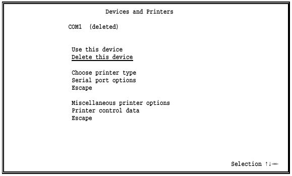
The same choices display for each COM device.
Use this device
Enable the COM device. You must select this option to enable the device before you can use it. The selected COM device displays as a destination device on the Assign Devices screen.
Delete this device
Default. Disable the COM device and remove it from the Assign Devices screen. The status (deleted) displays next to the device name at the top of the screen. The Assign Devices screen is easier to read if you disable devices you do not intend to use.
 Performance Tuning: Disable any serial devices you
do not use. This frees buffers and makes them available to other program
features.
Choose printer type
You must choose the type of printer to use. When you select this option, a list of printers displays. Section 8.6 describes the printer choices. After you make a selection, your choice displays on the Devices and Printers menu, next to the device name.
Serial port options
You must specify additional information about the COM port. The mode of the serial port (including baud, parity, data bits, and stop bits) must match the mode of the device attached to the serial port. Consult your serial devices user manual for the mode settings. When you select this option, the Serial Port Options screen displays. See Serial Port Options later in this section for more information about this screen.
Miscellaneous printer options
Several options affect printer performance. For a description of these options, see Miscellaneous Printer Options for COM Devices later in this section.
For a description of other options that affect printing, see section 18.2, Tuning and Global Options, Printer Control.
Printer control data
Printer control data is used to send control codes to the printer, such as commands to set the lines-per-form and lines-per-inch, or commands to reset the printer. You can use printer control data alone or with Barr printer forms. Section 8.8 tells you how to set up this feature.
Escape
This option appears twice on the screen. Select Escape or press the ESC key to return to the Devices and Printers menu.
The serial port and serial device settings must match.
 Select Serial
port options from the COM
device screen.
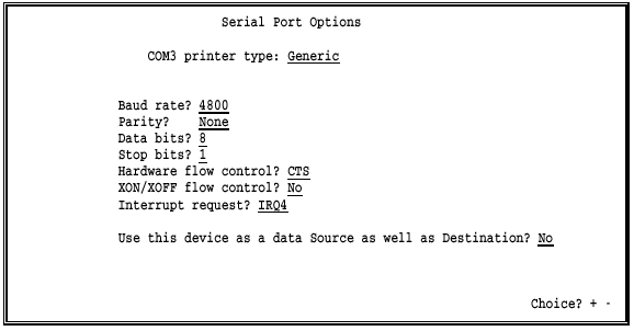
Baud rate? 4800|9600|19.2K|38.4K|57.6K|115K|110|150|300|600|1200|2400
The baud rate (in bits per second) controls the rate at which data bits are transmitted. The receiver and sender must transmit at the same rate. Which speeds your PC supports depends on the COM port in your PC.
 Performance Tuning: To achieve rates above 9600 bps,
you might need a PC with a Pentium processor and a COM port with a buffering
16550 UART chip.
Parity?
A parity bit can be added to each transmitted character to aid in error detection. The parity selection must be the same for both the sender and receiver.
None Default. No parity.
Odd Sum of 1 bits is odd.
Even Sum of 1 bits is even.
Data bits?
Specify the number of bits transmitted for each character. The number of data bits for both the sender and receiver must match.
8 Default. Eight bits are required for binary data.
7 Typically this value is not used, although it works for seven-bit ASCII data.
Stop bits?
Data travels on a serial line as a 1 or 0. The beginning of a data string is indicated by one start bit. The end of a character is indicated by one or two stop bits. Choose the number of stop bits required by the receiver.
1 Default. One stop bit is used at the end of each character.
2 Two stop bits are used at the end of each character.
Hardware flow control?
Specify whether the serial printer uses hardware flow control. Flow control prevents congestion of data caused by one device transmitting data faster than another device can receive the data. Some printers use XON/XOFF flow control, some printers use hardware flow control, and other printers use both.
A printer that uses hardware flow control uses a signal on an RS232 pin to show that it is ready to receive data. The printer cable normally connects this signal to Clear-To-Send on the PC serial port. The serial port interface is described in Appendix C.
CTS Default. Test Clear-To-Send (CTS) before sending data.
DSR Test Data-Set-Ready (DSR) before sending data.
DSR & CTS Test both Data-Set-Ready and Clear-To-Send before sending data. The Status Line on the Operation screen indicates which of the signals is low. If both signals are low, DSR=0 is used. DOS uses this flow control method.
None Do not test CTS or DSR. Use this choice for printers that do not use hardware flow control but use only XON/XOFF flow control.
To determine whether you have selected the correct flow control option, check the Status Line on the Operation screen. When you set the printer offline, the Status Line displays XOFF, CTS=0, or DSR=0. When you set the printer online, the Status Line displays normal. For more information about the Status Line, see section 20.2.
XON/XOFF flow control?
XON/XOFF is a type of software flow control. For a general discussion of flow control, see the Hardware flow control option.
No Default. XON/XOFF flow control is not used.
Yes Some plotters and printers use XON/XOFF flow control to prevent overrun on the data line when the printer or plotter is busy.
The XOFF character from the printer suspends output. XOFF is the ASCII DC3 character and is coded as hexadecimal 13.
XON resumes output to the printer. XON is the ASCII DC1 character and is coded as hexadecimal 11.
The flow control mechanism ignores the parity of XON and XOFF characters.
Interrupt request? IRQ7|IRQ9|IRQ10|IRQ11|IRQ12|IRQ15|IRQ2|IRQ3|IRQ4|IRQ5
This option displays only for COM3 or COM4. Specify the interrupt request to use with the serial port. Each COM port must have a different IRQ setting. (COM1 uses IRQ4 and COM2 uses IRQ3.) If two COM ports are set to the same IRQ, an error message displays.
Use this device as a data Source as well as Destination?
Data can be input to or output from a serial port. When data is input, the serial port is called a data source. When data is output, the serial port is a data destination. Source and destination devices are discussed in sections 8.1 and 10.3.
No Default. The serial port is used only as a destination.
Yes Data can be input on the serial port. You can use a serial port as a source, a destination, or both. You can route input from a serial port to any destination device, and you can route output from any source device to a serial port.
When you press ENTER, the Serial Port Source Options screen displays. The following section describes the options you must specify.
When you input data on the serial port, the serial port is called a source device. This section discusses serial input sample applications, error handling, and software options.
Serial input has several applications. You can do the following:
Send data to a printer. Data input on a serial port can be written to a file or sent to a printer attached to a PC parallel port, a PC serial port, or the LAN. Use the Assign Devices screen to specify the destination device.
Send a job to the host. Job control statements can be automatically added to a file input on the COM port. The job control statements, or JCL, form the data into a job to submit to the host. You enter the job control statements as a serial port input header from the Printer Control Data screen. Section 8.8 describes the special control characters required to set up the serial port input header.
Send
a command to the host. Data to be input on the serial port can
include a command to the host at the beginning of the input file. This
feature lets you automatically issue a command to the host immediately
before you send a file to the host. The command is sent to the host with
the device assignment KEYBOARD COMMAND. Any data that follows the command is
sent to the destination assigned to the COM device (for example, COM1
 RD1).
RD1).
To use the command-to-host feature, include a backslash (\) as the first character of the original file. When the file is input on the serial port, BARR/RJE checks for the beginning backslash. Data that follows the backslash is sent as a command to the host, as if you had issued it with the Command to Host option on the Operation screen. Terminate the command with a carriage return or an end-of-file marker. (You define the end-of-file marker on the Serial Port Source Options screen.) You can include consecutive commands at the beginning of the file. Precede each command with a backslash and end each command with a carriage return.
The Command
to Host option (selected from the Operation screen) and
the leading backslash feature (input from the serial port) require you
to assign KEYBOARD COMMAND on the Assign Devices screen. Section
21.2 describes the Command
to Host option.
If a receive error occurs during input from the serial port and it causes a character to be lost, the software inserts a question mark (?) in the file and displays this error message on the console:
Input from COM1 lost, a ? is substituted for lost character.
This error condition might be produced when software other than BARR/RJE (such as LAN or device driver software) turns off interrupts or when data transmission errors occur.
If a serial device is used as both a data source and a destination and XON/XOFF flow control is specified, XON/XOFF flow control will work in both directions.
When you input data on the serial port, you need to set the options described in this section.
 From the Serial Port Options screen set Use this device
as a data Source as well as a Destination to Yes.
The following screen displays.
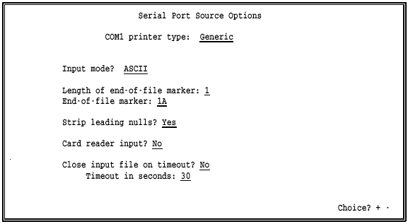
Input mode?
Select the character set of the data to be input on the serial port.
ASCII Default. Data to be input on the serial port is in ASCII format. To determine the end of the input file, the software checks for the end-of-file character you specify with the End-of-file marker option. When BARR/RJE reaches the end of the file, it adds the DOS end-of-file character, hexadecimal 1A, before it routes the file to the destination device.
If you set the End-of-file marker option to a value other than 1A, BARR/RJE performs additional processing. The software converts any 1A characters in the data to a tilde (~) because 1A is the end-of-file marker used by DOS. Converting these characters prevents DOS from prematurely ending the file.
 If you send the serial input data to the mainframe by assigning
it to a host reader (for example, COM1
 RD1) on the Assign Devices screen, the reader
device converts ASCII data to EBCDIC. This is the same conversion performed
when you set SEND1
 RD1 and use the Send Files command.
 Any file that begins with a leading backslash (\),
which signals a command to host, will be forced to ASCII input mode.
Binary Data to be input on the serial port is in binary format.
To determine the end of the input file, the software checks for the the end-of-file character you specify with the End-of-file marker option. Unlike ASCII input mode, when the end of the file is reached, the DOS end-of-file character is not added.
If you use binary input mode, XON/XOFF flow control is not recommended.
 If you send the serial data to the mainframe by assigning
it to a host reader (for example, COM1
 RD1) on the Assign Devices screen, the usual
ASCII to EBCDIC data conversion is not performed. This is the equivalent
of setting SEND1
 RD1 and using the Send Files command with the /B
option for binary send mode. See section
21.4 for more information about the Send Files command and binary
send mode.
Length of end-of-file marker:
Specify the length of the end-of-file marker. The maximum value is 8. BARR/RJE recognizes the end-of-file marker that it receives from the serial port. The default end-of-file marker is the one-byte, hexadecimal 1A used by DOS and VAX/VMS. If you set Input mode to Binary, use a four-byte end-of-file marker.
End-of-file marker:
Enter the end-of-file marker as hexadecimal digits. The entry line reflects the length specified by the previous option. The default value, 1A, is the end-of-file marker used by DOS and VAX/VMS.
Strip leading nulls?
Choose whether to strip leading nulls from the beginning of files input on the serial port. Nulls are sometimes sent by a serial device when you power it on.
Yes Default. Strip leading nulls from files.
No Do not strip leading nulls.
Card reader input?
If you plan to receive data from a card reader, select how the end of file will be handled. Some card readers generate additional characters after the end-of-file marker which, if not discarded, would cause BARR/RJE to open a new file. Your selection depends on how your card reader signals the end of file.
No Default. Data will not be input from a card reader. The end-of-file marker is handled normally.
Yes Data will be received from a card reader. After the end-of-file marker has been detected, all characters are discarded up to and including the next carriage return. This is the most common method.
Verify Check that each card contains 80 bytes.
If Input mode is ASCII, the software verifies that after every 80 data columns there is a carriage return and line feed (CR LF) and includes them in the data file.
If Input mode is Binary, the software verifies that after every 80 data columns there is a carriage return (CR) and then discards the carriage return.
If a character is lost during data input, the job is canceled and the next job will start after the end-of-file card.
FF After the end-of-file marker has been detected, all characters are thrown away up to and including the next form feed.
Close input file on timeout?
This option can release the COM port if the source device becomes disabled while sending a file or if the end-of-file marker is accidentally omitted from the file. When the COM port is not released, the port remains busy and other data cannot be sent or received on the port.
No Default. The file is not closed until an end-of-file marker is detected.
Yes If an end-of-file marker is not detected, the file is closed after the timeout period specified by the Timeout in seconds option.
Timeout in seconds:
If data input on the serial port stops, the software will close the input file after the specified period of time. This time period during which no data is received is called a timeout and is measured in seconds. After the file is closed, the data is sent to the destination device.
The default timeout period is 30 seconds. Valid values range from 0 to 999 seconds. You can use the timeout feature with the end-of-file marker to indicate the end of a file.
The timeout option is valid only if you set Close input file on timeout to Yes.
You can use several printer options with COM devices to simplify print data processing or to solve printing problems.
 From the Devices and Printers menu for the selected COM
device, select Miscellaneous
printer options.
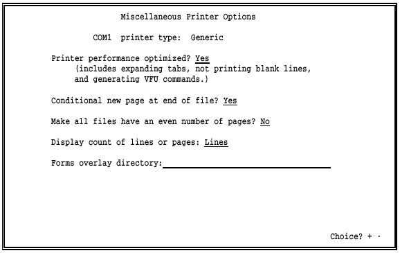
Printer performance optimized?
Choose whether to optimize printer performance by converting data as it is sent to the printer.
Yes Default. Printer performance is improved by changing the data as follows:
Blank lines are converted to line feeds (LF).
If the printer has Direct Access Vertical Forms Unit (DAVFU) support, the hardware skip-to-VFU channel commands are used to perform high-speed skipping of blank lines. DAVFU is a Dataproducts convention for specifying vertical forms control.
Horizontal tab characters are converted to the required number of blanks to emulate tab settings at eight-character intervals.
No Data is not changed when it is sent to the printer.
Conditional new page at end of file?
Choose whether the software should add a form feed (FF) to the end of a file, if needed. This option ensures that each file begins at the top of a new page, which is helpful when form feeds are missing from some files.
Yes Default. At the end of each file, the software determines whether a form feed is included or whether the maximum page length is reached. One of these conditions is necessary to ensure that the next file begins at the top of a new page. If neither condition is met, the software adds a form feed. The software remembers if it adds a form feed, and if the next file contains a form feed at the beginning, the software removes it to prevent printing a blank page.
No Form feeds are not added to or removed from files.
Make all files have an even number of pages?
Choose whether all files should have an even number of pages for easier job separation.
No Default. The number of printed pages can be even or odd.
Yes If a file has an odd number of pages, add a blank page to make the number of pages even. This ensures that the job banner page always faces up on the fan-fold paper stack.
Display count of lines or pages:
This option controls the count of lines or pages printed that appears on the Operation screens Status Line and in the Print Spool screens Units column. For more information about the Status Line, see section 20.2. For more information about the Print Spool screen, see Chapter 24.
Lines Default. Display the number of lines printed. This choice is typically used for line printers.
Pages Display the number of pages printed. This choice is typically used for laser printers.
Forms overlay directory:
Use the forms overlay feature to load electronic forms or to send additional printer control data or printer resources to the printer.
In this field, enter the name of the directory where overlay files are stored. Include the drive letter and full directory path. Remember to create the actual directory with the DOS make directory (md) command. If you do not intend to use this feature, leave the directory name blank.
For more information about this feature, see section 8.7.
When you route print output to network printers, you need to set the options described in this section. The NET devices can use a device driver, Novell print queue, or TCP/IP LPR (UNIX) print queue to route files to printers. You can use different types of network printers. Each NET device uses a separate set of printer control data.
From the Devices and Printers menu, select NET1-12.
A list of NET devices displays.
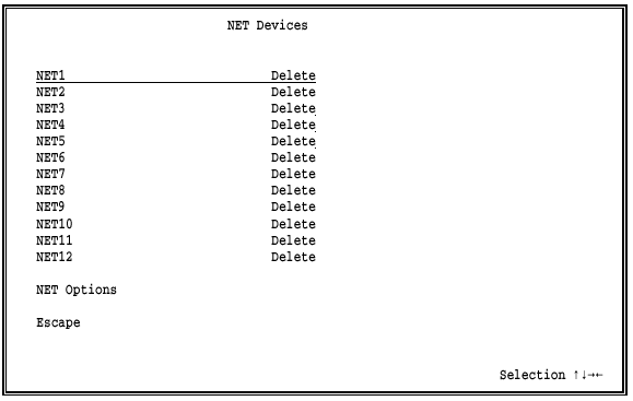
Select NET1.
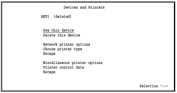
The same choices display for each NET device.
Use this device
Enable the NET device. You must select this option to enable the device before you can use it. The selected device displays as a destination choice on the Assign Devices screen.
Delete this device
Default. Disable the NET device and remove it from the Assign Devices screen. The status (deleted) displays next to the device name at the top of the screen. The Assign Devices screen is easier to read if you delete devices you do not intend to use.
Network printer options
Select which type of network printer to use. Choices are Novell Print Queue, Device driver, and TCP/IP LPR (UNIX) Print Queue. When you press ENTER, additional information displays on the second half of the screen. See Network Printer Options later in this section for a description of these options.
Choose printer type
You must choose the type of printer to use. When you select this option, a list of printers displays. Section 8.6 describes the printer choices. After you make a selection, your choice displays on the NET Devices screen next to the device name.
Miscellaneous printer options
Several options affect printing. For a description of these options, see Miscellaneous Printer Options for NET Devices later in this section.
For a description of other options that affect printing, see section 18.2, Tuning and Global Options, Printer Control.
Printer control data
Printer control data allows you to send control codes to the printer, such as commands to set the lines-per-form and lines-per-inch or commands to reset the printer. You can use printer control data alone or with Barr printer forms. For network printers, printer control data has a special function. For more information, see Printer Control Data for Network Printers later in this section.
Escape
This option appears twice on the screen. Select Escape or press the ESC key to return to the Devices and Printers menu.
On the Network Printer Options screen, specify how files are routed to network printers.
 From the Devices and Printers menu for the selected NET
device, select Network
printer options.
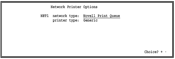
network type:
Choose which type of network printer to use. After you make a selection, additional options display on the lower half of the screen. Three choices are available.
Novell Print Queue Default. Direct the output files to the specified Novell print queue. This choice allows you to route files to any print queue on the Novell network. See Novell Print Queue later in this section.
Device driver Direct the output files to the specified DOS device driver. See Device Driver later in this section.
TCP/IP LPR (UNIX) Print Queue Direct the output files to the specified LPR print queue. To see this choice, you need to request a special version of software from Barr Systems. See TCP/IP LPR (UNIX) Print Queue later in this section.
printer type:
The printer type you select on the Printer Type screen displays here.
When you select Novell Print Queue as the NET device network type, you need to set the options described in this section.
On the network, files are stored in queues while they wait to be printed. Queues reside on network file servers. The software uses NET devices to write files to the network print queues.
For each NET device, you can route all output to one print queue on a specific file server, or you can route output to different print queues on any server by using the print file's FCB name or form name as routing criteria.
The number of Novell print queues you can access is determined by the number of NET devices you define and the number of entries you make in the FCB/FORM to Print Queue Translation Table.
The Novell network allows a PC to connect to a maximum of eight different file servers at a time. For the NET devices, the Barr software BARR/RJE logs into and out of servers as needed to access additional queues. The software connects to the servers as a network user with print queue rights.
Of the eight possible server connections, the number available for the NET devices depends on how many server connections are being used for other purposes. The PC can log into file servers when you power it on, before the Barr software starts. These server connections are used to access network drives, and BARR/RJE cannot log out of them. The Barr LAN connections feature can use these connections.
If you receive data on the Novell NetWare queue devices (NW_QUEn) described in section 8.11, BARR/RJE will use another network connection. For the Novell queues, the software will log into one file server as a print server. This connection is different from the user connection made by the NET devices. During software operation, BARR/RJE will not log out of the Novell queue connections either. Because Novell does not allow a PC to log into the same file server as both a user and a print server, the NET devices cannot access the same server used by the Novell queues.
If you select Novell Print Queue as the NET device network type, the following options display on the lower half of the screen:
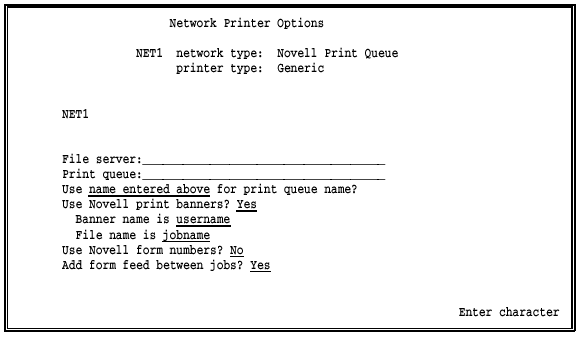
File server:
Print queue:
If you want to route all output for the NET device to one print queue, enter the File server and Print queue names. When you route output for this NET device to many devices by FCB name or form name, you can leave these fields blank or you can enter a default value in case of an error condition. (See FCB/FORM to Print Queue Translation Table later in this section.)
The software can be logged into a maximum of eight different file servers at one time. See Network Connections earlier in this section for a discussion of the available server connections.
Use ___ for print queue name?
Output is routed to the print queue specified by this option. Three choices are available.
name entered above Default. Use this choice if all output for this NET device will be directed to only one print queue on a file server, as specified in the File server and Print queue fields above.
FCBNAME
FORMNAME
Output can be routed to any print queue on any file server
by using the FCB name or form name specified in the file. The FCB/FORM
to Print Queue Translation Table displays when you choose either FCB name
or form name. Use the translation table to associate the FCB name or form
name in the file with a file server and print queue. The software routes
files to the Novell queues you specify in the table entries.
To include the FCB name and form name information in the file, you can use the normal host means of specifying the FCB name and form name (usually the $HASP190 message or SETUPHDR record), the Barr OUTPUT statement used in file option, or the Barr Spool header from data option (provides form name only).
See FCB/FORM to Print Queue Translation Table later in this section.
 RJE+3270: If you have RJE+3270 software, you can use
this method only for RJE data streams, not 3270 streams.
Use Novell print banners?
Choose whether to use Novell print banners.
Yes Default. BARR/RJE provides information to Novell so it can build a print banner page. Banner pages are useful for identifying printouts. They include the file server and print queue names from the Network Printer Options screen and the user name from the NET Options screen. You also can use the next two options to specify additional banner information. This feature works for jobs received from the host on either the printer (PRn) or punch (PUn) streams.
No Do not generate print banners.
Banner name is
If you enabled Novell print banners with the previous option, select which information to include on the lower half of the banner page.
Choose from username (the default), fcbname, not used, formname, and jobname. If you select not used, none of these fields are included on the banner page. If you choose fcbname, formname, or jobname, the corresponding name from the spool header or host data stream will print on the banner.
 RJE+3270: If you have RJE+3270 software, note that
the job name is not included in 3270 data streams and thus cannot be included
on the print banner.
File name is
If you enabled Novell print banners, select which information to display in the file name field of the banner.
Choose from jobname (the default), username, fcbname, not used, and formname. If you select not used, the file name field will be blank. If you choose fcbname, formname, or jobname, the corresponding name from the spool header or host data stream will print in the banner's file name field.
 RJE+3270: If you have RJE+3270 software, note that
the job name is not included in 3270 data streams and thus cannot be included
on the print banner.
Use Novell form numbers?
This option allows you to control Novell form number processing for NET devices. The Novell PRINTDEF utility is used to define forms on the network print queues.
No Default. Novell form numbers are not used.
Yes The mainframe form number stored in the Barr spool header is passed to the Novell Print Queue so that a Novell form can be used when the file is printed. If the form name in the spool header is not numeric, the Novell form number is set to zero.
Add form feed between jobs?
This option is useful when you send jobs to laser printers. It ensures that the last page of the job is flushed from the printer before the next job starts.
Yes Default. Form feeds are added between print jobs.
No Form feeds are not added.
If you select Device driver as the NET device network type, the following field displays on the lower half of the screen:

Device name:
Enter the DOS device name for the network printer. You can specify the name of a device or a file. Common device names are LPT1, LPT2, or LPT3. If you specify a device, you must enable network redirection of the device on the network. See your network manager if you need assistance.
If you specify a file name, the file extension is optional. When BARR/RJE writes to a file, any files with duplicate names are renamed using automatic generation of numeric file extensions. The software assigns the first file with a duplicate name an extension of .001, the next file with that name an extension of .002, and so on. For an example of the automatic naming sequence, see File Name Extensions in section 10.5.
Support for TCP/IP LPR print queues lets you route files from the PC to BSD TCP/IP print queues (per RFC 1179) on an LPD server. For example, you can route files to print queues on a UNIX host. The LPR protocol writes to an LPD at the specified IP address. LPR is used to submit jobs to LPD print queues and LPD manages the print queues. You can request software with this option from Barr Systems.
This feature requires FTP Software's PC/TCP kernel, version 2.2 or later. PC/TCP provides the PC interface to the TCP/IP network.
The number of TCP connections is limited only by the number of NET devices you define. Because the Barr software supports 12 NET devices, up to 12 TCP connections are possible.
In the PC/TCP software, the default number of TCP connections is six. This value is specified as tcp-connections=6 in the PCTCP.INI file. If you need more than six connections, increase this value in the PCTCP.INI file.
When you use the LPR option, you must direct files to the LPR queue from the print spool.
If you select TCP/IP LPR (UNIX) Print Queue as the network type for the NET device, the following options display on the lower half of the screen:
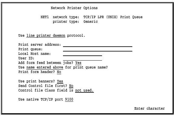
Use ___ protocol.
Select which protocol to use for the TCP/IP NET device.
line printer
daemon Default. Files must be directed to a destination
that uses the LPD protocol. This choice requires that the file writes
to the print spool before it is directed to the final destination (for
example, SPOOL1 NET1) so BARR/RJE can determine the file size
and provide it to the LPR/LPD protocol. Before it can process files, LPR/LPD
must be informed of the exact file size. The LPR file size includes the
size of any overlay files.
native TCP/IP Files must be directed to a destination that uses the native TCP/IP protocol. Files do not have to be written to the PC disk before you send them. This choice is useful when BARR/RJE communicates PC to PC across TCP/IP, where the other PC running BARR/RJE is on a different LAN. For example, you can receive data on one Barr PC and send it across the Internet to another Barr PC (with the BARR/PRINT for TCP/IP option) where it will be printed.
Print server address:
Enter the IP address or equivalent host name of the print server where files will be sent.
Print queue:
The name of the print queue on the print server. If you select native TCP/IP as the protocol, this field is optional.
Local Host name:
A name indicating the Barr PC node name. When you view a queue of files on a host, it is helpful to determine the file source. The local host name is added to the LPR/LPD control file on the host and is required by some LPDs.
User ID:
The name of the user submitting the job. You must specify the same user ID for all your NET devices. When you view a queue of files on a host, the user ID helps you identify who submitted the file. The user ID is added to the LPR/LPD control file that is sent with the print file and is required by some LPDs.
Add form feed between jobs?
Specify whether to add a form feed (FF) between jobs for easier job separation.
Yes Default. Insert a form feed between jobs to separate jobs with a blank page.
No Do not add a form feed between jobs.
Use ___ for print queue name?
Specify the print queue to which BARR/RJE will route output. Three choices are available.
name entered above Default. Use this choice if you will direct all output for this NET device to only one print queue on a file server, as specified by the Print server address and Print queue fields.
FCBNAME
FORMNAME You can route output to any print queue on any
file server according to the FCB name or form name specified in the file.
When you choose either FCB name or form name, the FCB/FORM to Print Queue
Translation Table screen displays. The translation table associates the
FCB name or form name in the file with a file server and print queue.
The software routes files to the LPR queues specified in the table.
To include the FCB name and form name information in the file, you can use the normal host means of specifying the FCB name and form name (usually the $HASP190 message or SETUPHDR record), the Barr OUTPUT statement used in file option, or the Barr Spool header from data option (provides form name only).
See FCB/FORM to Print Queue Translation Table later in this section.
 RJE+3270: If you have RJE+3270 software, you can use
this method only for RJE data streams, not 3270 streams.
Print form header?
Choose whether to process or send the Barr spool header.
No Default. BARR/RJE converts the spool header information to printer instructions and sends them to the destination device. You can use this choice if you select line printer daemon as the protocol.
Yes BARR/RJE sends the spool header so the receiving PC can process the header information. You can use this choice for either the line printer daemon or native TCP/IP protocols.
Use print banners?
Choose whether to include banner pages in print jobs. You can use banner pages to help identify printouts. This option is valid only if you select the line printer daemon protocol.
Yes Default. The Barr software sends a request to the LPD server to generate a banner page. The LPD server uses information from the control file - including the job name, host name, user name, file name, and class name - to build the banner.
No The software does not send a banner page request.
Send Control file first?
An LPR print job consists of two files: a data file and a control file. The data file contains the print data and the control file contains attributes describing the print data. You can choose whether the Barr software sends the control file first or last. This option is valid only if you select the line printer daemon protocol.
No Default. The software sends the control file last.
Yes The software sends the control file first.
Control file Class field is ___.
You can customize the value of the class field in the control file that the Barr software generates. This option is valid only if you select the line printer daemon protocol.
not used Default. The class field is not used in the control file.
FORMNAME The class field contains the form name.
JOBNAME The class field contains the job name.
Use native TCP/IP port
This option is valid only if you select the native TCP/IP protocol. Specify the port number that identifies the host connection. The default port number is 9100. You can change the value in this field, or you can specify a value in the Print queue field. The value from this field or the Print queue field also displays in console messages indicating device activity.
On the Network Printer Options screen, if you select FCBNAME or FORMNAME as the print queue name and press ENTER, the FCB/FORM to Print Queue Translation Table screen displays. The translation table is used to route files to specific print queues based on the FCB name or form name in the spool header.
One table applies to all NET devices with a network type of Novell Print Queue or TCP/IP LPR (UNIX) Print Queue.
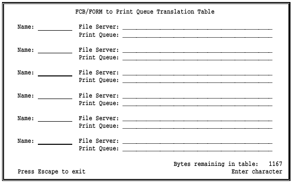
When it routes a file to a print queue, the software checks for the file's FCB name or form name in the translation table entries. You determine which value the software checks by your selection for Use __ for print queue name on the Network Printer Options screen.
If a match is found in the table, the file is routed to the corresponding file server and print queue. If a match is not found, the software performs the action described under Error Handling later in this section.
The FCB/FORM to Print Queue Translation Table has a fixed size in bytes and holds a variable number of entries depending on the number of bytes per entry. If the table entries are short, the table can hold a larger number of entries.
As you add entries to the translation table, the number of bytes available for additional entries is updated on the bottom right corner of the screen. The table size is 1,167 bytes, allowing it to hold 20 to 30 entries. If you need a larger table, you can request a special version of the software from Barr Systems.
To move between fields within a table entry, use the TAB or arrow keys.
Press ENTER to save the current entry and advance to the next entry.
To remove an entry, use the SPACEBAR to blank it out.
Press ESC to exit the table when you are done.
Table entries include these fields:
Name:
Specify the FCB name or form name that is included in the source file. FCB name or form name can be supplied by the host computer if you enable the host $HASP190 (SETUP=MSG) or SETUPHDR (PDIR) options. Or the software can provide the desired value if you use the Barr OUTPUT statement used in file option.
 You cannot use DOS wildcards in the entries for this table.
File Server:
Print Queue:
Enter the name of file server and print queue where jobs with the specified FCB name or form name will be routed.
You have two choices for handling any errors that might occur when table entries are used to route print files. For example, an error occurs if the FCB name or form name from a file is not listed in the table.
The output can be directed to a default printer. For this method, enter a default value for the File Server and Print Queue fields on the Network Printer Options screen.
The source device is set to Retry and an error message displays on the Barr console. Jobs with invalid form names will remain in the SPOOL directory and Retry messages will be displayed.
When a device is set to SUSPEND, the operator must correct the error from the Assign Devices screen. Change the destination from SUSPEND to a NET device that does not use the FCB/FORM to Print Queue Translation Table or to a NET device that has a default File Server and Print Queue. When the file finishes printing, change back to the original destination to resume normal file routing.
The NET Options screen contains options that affect all NET devices.
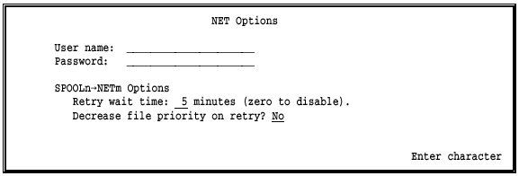
User name:
Password:
A User name and Password BARR/RJE uses to connect to file servers. You can use only one User name and Password to log into all the servers.
When you enter a password, asterisks (*) display for the password characters. BARR/RJE uses a keyed login to allow login on servers restricted to encrypted passwords.
During BARR/RJE operation, if the software already is logged into a given server with print queue rights, the existing login is used. No additional login is performed, even if the Barr software is logged into the server with a different user name than that specified in the User name field.
If the Barr software performs a login to connect to a print queue, the software will log out when the print job completes. BARR/RJE can be logged into only eight file servers at one time. If a login is needed but the software already is logged into eight servers, login is deferred until a print job completes and frees a server slot. If a NET device is unable to connect to the specified server/queue because the server/queue is unavailable, it will retry the connection repeatedly at five-minute intervals.
See Network Connections earlier in this section for a discussion of the available server connections.
Retry wait time: ___ minutes (zero to disable).
This option and the next one affect files that are directed from the
print spool to a net device (for example, SPOOL1 NET1). When
file transfer from a spool device to a NET device fails, choose whether
to put the spool file on hold or retry the transfer. If you specify 0
for this option, BARR/RJE puts the file on hold. If you specify a value
other than zero, BARR/RJE sets the spool state to Retry and waits the specified
number of minutes before re-attempting the transfer. The default value
is 5
minutes.
Decrease file priority on retry?
Choose whether to decrease the spool priority of files that are set to the Retry state.
No Default. The file priority is not changed.
Yes Decrease the file priority by 1. This allows new files that arrive in the spool to print first when many files are set to the Retry state. Otherwise, the print spool might continuously cycle between the files on retry and delay printing any new files.
Two printer options are available for each NET device.
 From the Devices and Printers menu for the selected NET
device, select Miscellaneous
printer options.
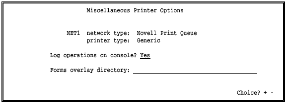
Log operations on console?
This option controls the console messages START NETn and END NETn. These messages display when output is sent to a NET device.
Yes Default. START and END messages display on the console when jobs are sent to the NET device.
No Status messages do not display on the console when jobs are sent to the NET device.
Forms overlay directory:
Use this feature to load electronic forms or to send additional printer control data or printer resources to the printer.
In this field, enter the name of the directory where the overlay files are stored. Include the drive letter and full directory path. Remember to create the actual directory with the DOS make directory (md) command. If you do not intend to use this feature, leave the directory name blank.
For more information about this feature, see section 8.7.
Printer control data has some uses that are especially important to NET devices.
It is important to send an appropriate reset string at the beginning of each file printed on a network printer. These printers print data from many different applications. Data from the Barr software might not print correctly unless the software sends the proper reset string.
You can enter a printer reset string in the Printer Control Data table for each NET device with a network type of Novell Print Queue or Device Driver. For more information about printer control data, see section 8.8.
You can use form overlay files to send reset strings to network print queues when you set the NET device network type to Novell Print Queue or TCP/IP LPR (UNIX) Print Queue and use FCB name or form name to route output to different types of printers. Set the Search for form overlay by option to FCBNAME or FORMNAME on the Tuning and Global Options, Printer Control screen. For more information about forms overlay, see section 8.7.
You must assign a printer type for each LPT, COM, and NET device you use.
From the Devices and Printers menu for the selected device, select Choose printer type.
A list of printer types displays.
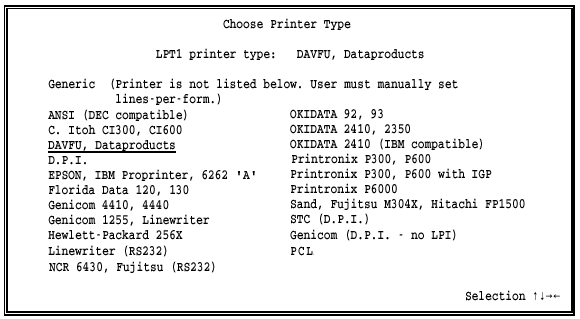
Select the printer type.
Except for the special selection Generic, all of the printers on this screen are line printers. For most selections, the Barr software automatically sets lines-per-form and lines-per-inch on the printer, so you do not have to adjust these settings manually. See Lines-per-form and Lines-per-inch later in this section for a description of the settings provided by the Barr software.
The printer type selections fall into three categories:
Laser printers (Generic), for which the software does not provide the lines-per-form and lines-per-inch settings.
Line printers for which the software sends lines-per-form and lines-per-inch control codes.
Line printers for which the software sends lines-per-form and lines-per-inch control codes and implements Vertical Forms Unit (VFU).
If your line printer is not listed on the screen, check Table 8-1 under Lines-per-form and Lines-per-inch for a compatible selection. Compare the control codes in the table to the control codes listed in your printer manual to determine if one of the selections will work.
Some printer type selections have specific requirements, as described in this section.
Generic
Use this selection for the following:
Laser printers
Line printers, only if you want to use settings other than the ones supplied by the software
You need to set lines-per-form and lines-per-inch by using either BARR/RJE settings (printer control data, forms overlay, or printer forms) or manual settings on the printer.
This selection also is useful if you do not want BARR/RJE to change the data. To prevent the data from being modified, you also must set Printer performance optimized to No under Miscellaneous Printer Options.
DAVFU, Dataproducts
Printronix P300, P600
When you use one of these printers, the Barr software sets only the lines-per-form. You must manually set the lines-per-inch on the printer.
D.P.I.
Use this selection only with the BARR/DPI adapter from Barr Systems. The BARR/DPI printer adapter and cable support all printers that use the Dataproducts Interface. The adapter can be configured for the devices LPT1, LPT2, or LPT3 and is fully compatible with BIOS and DOS. (The adapter is available in both long-line and short-line versions. The cable is available with either a Winchester connector or a D-type, 50-pin connector.)
Because the Dataproducts VFU feature is fully implemented in Barr software, the printer can jump directly to a specific line without printing blank lines. This results in faster printing.
The BARR/DPI adapter also supports extended ASCII codes (eight-bit data) such as the cent (’) sign. To use the extended ASCII codes, on the Miscellaneous Printer Options screen set Enable VFU download into printer to No. This disables optimization, but has no other effect on printing. If you do not disable optimization, you will get errors in the printed output.
Use of extended ASCII codes also disables the Paper Instruction (PI) line. With regular ASCII format (seven-bit data), the eighth data bit is sent to the printer's PI line. The PI line is driven only for printer control data or DAVFU commands. With extended ASCII format, the eighth data bit is used as data so the PI line is idle.
The D.P.I. selection supports up to 255 print lines per page and carriage control stops appearing on lines 1 to 240.
Genicom (D.P.I. - No LPI)
This printer type is similar to the D.P.I. selection but does not send the lines-per-inch setting to the printer. Use this selection for printers that supply the lines-per-inch setting but need the software to set the lines-per-form. The Genicom 1255 is an example of such a printer.
Control codes, also called escape sequences, are used to specify lines-per-form, lines-per-inch, and other format settings for printers. Your printer manual describes the control codes used for your printer. Barr software supplies the most common codes used for various printers. See your printer manual for a list of the control codes your printer supports.
Table 8-1 shows common control codes for the printers listed on the Choose Printer Type screen. Values for lines-per-form and lines-per-inch are provided either by form information in the original file or by a form you created with BARR/RJE. These values are stored in the Barr spool header. When the software sends data to the printer, it interprets the value for these settings and sends the corresponding escape sequences to the printer.
If the host computer supports the FCBLOAD option, FCBs can be used to include lines-per-form and lines-per-inch values in the file before it arrives at the PC. Or, the Barr software can provide these values using the printer forms feature. If the lines-per-form (LPF) and lines-per-inch (LPI) values are not provided, the software uses the default values LPF=66 and LPI=6.
If your printer is not listed in Table 8-1, determine whether one of the printers in the table provides the control codes used by your printer. If the correct codes are listed, select the corresponding printer from the Choose Printer Type screen. If the codes for your printer are not listed, use the Generic selection and enable another Barr feature (printer control data, forms overlay, or printer forms) to provide the control codes.

*Double question marks (??) in the control codes represent characters with no ASCII equivalent.
You can use the Barr forms overlay feature to print electronic forms or to send printer control data or printer resources to the printer. These applications are described below.
When BARR/RJE is ready to print a file, it searches the forms overlay directory for a specific overlay file. If BARR/RJE finds the overlay file, it sends the overlay file to the printer before the print file. BARR/RJE can send another overlay file at the end of the print file.
To set up the forms overlay feature, you must specify the name of the directory where you will store the overlay files for each device. For the LPT, COM, or NET devices, the overlay directory name is on the Miscellaneous Printer Options screen. If you have the PRINT370 option, the overlay directory name is on the Printer Options screen for the S/370 channel-attached printer.
You also must set the forms overlay options on the Tuning and Global Options, Printer Control screen, as described in section 18.2.
All overlay files must be named with the same convention. You can name them for the form name, FCB name, job name, or UCS name. Specify the naming convention with the Search for form overlay by option on the Tuning and Global Options, Printer Control screen.
Electronic forms are a replacement for preprinted forms. The forms overlay feature of many laser printers allows an electronic form to be printed automatically with every page of a data file. You can then use plain paper instead of preprinted forms paper. For example, the software sends the text of an invoice form to the printer only once and the printer loads it as an overlay. Next, the software sends the data file, and each page of data is overlaid with the invoice form, so that both the form and the data print on the page.
To create electronic forms, you need a form design package. Use the software to create forms and insert special printer codes. You must store the completed forms as overlay files in the BARR/RJE forms overlay directory. When the Barr software is ready to print a file, it checks the forms overlay directory and sends the corresponding form overlay file to the printer before it sends the print file.
For more information about form design packages and form management, request the Electronic Forms Management booklet from Barr Systems.
You can use the forms overlay feature to send printer control codes to the printer as an alternative to using the Printer Control Data screen in the Barr software. The forms overlay method is especially useful if you need to enter more printer control codes than you can fit on the Printer Control Data screen. You must use a program editor to enter the printer control codes in the overlay file in hexadecimal format. You can send one overlay file before and another one after the print job. For example, the starting overlay file can set up the printer and the ending overlay file can reset the printer, as described in section 18.2.
To print certain types of files, some printers require additional resources to be loaded. You can put files containing printer resources in the overlay directory for automatic loading by the Barr software. For example, the SNPFORM and SNPIMAGE utilities for Ocι printers are used to generate additional fonts or other resources. These files are placed in the forms overlay directory.
Barr software can convert data from EBCDIC to PostScript format. To enable this feature, you need the Barr overlay files 2UP, LAND, and PORTRAIT included with the Barr reference files. You can edit these files and copy them to the forms overlay directory.
You also must set the receive mode for the host printer or punch device to PostScript on the Assign Devices screen. For more information about PostScript receive mode, see section 10.8.
You can include several overlay files in a single file by using the Barr embedded send files command, ##. The master file contains send commands referencing the other files. This feature allows you to store common overlay features in separate files so they can be shared. Otherwise you might have to store duplicate copies of the same overlay text and commands in several different overlay files.
 When you use ending overlay files, you cannot use the embedded
send command in either the beginning or ending overlay file of a beginning/ending
overlay file pair.
Follow these steps to create an overlay file composed of other files.
Use an ASCII editor or a program editor to create individual overlay files containing the features you want. For example, create one file that contains a font code and another file that contains a company logo.
Use the editor to create a master overlay file that references the files containing the features you want. The form of the send command is:
##file1 file2 ... filen
Follow these rules when you type the file name list:
The embedded Send Files command, ##, must be at the beginning of the list.
Separate the file names with a space, tab, or blank line.
If the files are not located in the overlay directory, specify the full directory path as part of each file name.
The overlay file containing the list can have a maximum size of 512 bytes.
For example, you can create an overlay file that includes a tax form, a company logo, and the courier font from three other files. First, create a file named TAXFORM that contains the form text, a file named LOGO that contains the company logo, and a file named COURIER that contains the courier font code. Next, create an overlay file named TAXES that contains this text:
##taxform logo courier
When a job with the form name TAXES is ready to print, the files containing the tax form, the logo text, and the courier font are loaded into the printer as an overlay. Additionally, the TAXFORM, COURIER, and LOGO files can be listed in other overlay files you create.
Printer control data is an optional feature for LPT, COM, and NET devices that you can use to control special functions of the printer. For example, you can set the page mode (portrait or landscape), page size, lines-per-form, lines-per-inch, characters-per-inch, and typeface.
On the Printer Control Data screen, you enter codes for these printer functions as strings of characters in hexadecimal format. Each control string is terminated by two bytes of hexadecimal zeros (00 00). When the software sends a file to the printer, it sends the codes to the printer before the file. Some strings can be sent at the end of the file.
This section tells you how to enter control codes on the Printer Control Data screen, describes special control characters, and gives several control code examples. The control codes vary from printer to printer and are documented in your printer manual. Printer control data also can be linked to printer forms, as described in sections 13.2 and 13.3.
From the Devices and Printers menu for the LPT, COM, or NET device, select Printer Control Data.
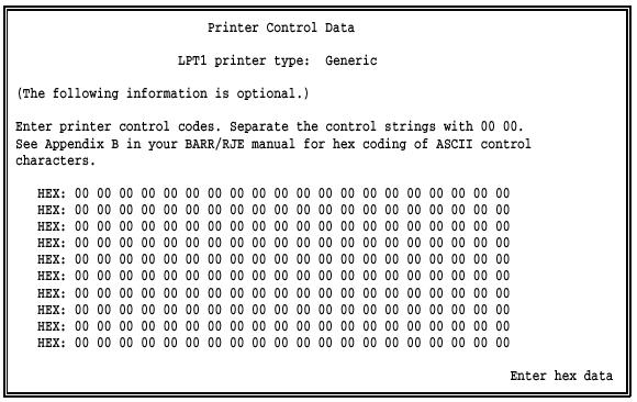
Enter the printer control data as pairs of hexadecimal digits.
As you enter each code, the corresponding ASCII character displays in the space after the code.
The Printer Control Data screen has 10 entry lines that can hold up to 20 control characters each. If you need to enter more printer control codes than you can fit on this screen, you can create files containing these codes instead. Use a program editor that supports entry of hexadecimal codes to create the files, then use the forms overlay feature to send the codes to the printer. See section 8.7 for a detailed description of the forms overlay method.
Follow these guidelines for entering control codes.
Use the arrow keys to move around the screen.
If you make an error, you can use the ESC key to return the screen to its original values.
When you press ENTER, the new values are stored. The ESC key will not clear stored values. You can type over any stored values you want to replace.
You can link printer control data to Barr printer forms that you create with the Edit Forms option. See sections 13.2 and 13.3.
In the Printer Control Data table, different types of control strings are distinguished by special control characters. Applications for the various control strings are described below.
String separator. Each control string must be terminated by two pairs of hexadecimal zeros (00 00). Strings do not have to start on a new line. A string that begins on one line can wrap to the next line.
Start-of-file string. A string that begins in the first position of the table is sent to the printer at the start of every file. If you do not want to use this type of string, begin your table entries after the first two pairs of zeros (00 00).
End-of-file string. A string that starts with FF is sent to the printer at the end of every file. You might want to use a string beginning with FF to reset the printer after each job, especially if the printer is shared by the Barr PC and users on the network.
Printer form string. Strings that start with the bytes 01 to FD are sent to the printer when they are referenced by a Barr printer form. This lets you use a Barr form to control features such as landscape and portrait page mode on a laser printer. See sections 13.2 and 13.3 for more information about linking printer control data to Barr printer forms.
Serial port input header. A string beginning with FE is called a serial port input header and is used differently than other control strings. Rather than being sent to the printer as control codes, this string is appended to the beginning of all files input on the selected serial (COM) port. You can use the serial port input header to include commands to be sent to the host or insert Job Control Language (JCL) so the file can be submitted to the host as a job. If the header is composed of multiple lines, indicate the line breaks by inserting a hexadecimal 0D (carriage return). See Example 4 later in this section and Serial Port Source Options, Sample Applications in section 8.4.
These examples show how you can use printer control data. Each example shows codes for a different type of printer. See section 13.3, Using Printer Control Data with Forms, for additional examples of using printer control data with printer forms.
This example describes control characters used for the Xerox 2700.
You might want the printer to ignore a form feed (FF) character that occurs as the first byte of the print file. This prevents blank pages from printing between jobs. If you enter 0C (the ASCII form feed character) as the first byte of printer control data, the printer will ignore the form feed. To enable the offset stacker feature at the start of every file, enter 1B 6F.

In this example, the hexadecimal code 1D causes the OKIDATA 92 and 93 printers to print in a compressed 132 characters-per-line mode.

You might want to use control codes when the printer is shared by the Barr PC and users on the network. In this example, control strings cause files sent by the Barr software to print in a compressed-text format and files sent from other sources to print at a normal density.
The control code 0F causes the EPSON/IBM printer to print compressed text at a density of 132 characters-per-line. To reset the printer at the end of each file, use the end-of-file string that begins with FF. For the EPSON/IBM printer, the reset code is 12. Each control string is terminated with a 00 00 sequence.

The serial port input header starts with FE. BARR/RJE adds this control string to the beginning of each data file input on the selected serial (COM) port, rather than sending it to the printer as control codes. This example shows how to insert Job Control Language (JCL) at the beginning of files as they are input on the serial port so the files can be submitted to the host as jobs. The control codes shown below are the hexadecimal translation of the following JCL:
//XX JOB ACCOUNT
//EXEC WORK

When network printers are shared by other users on the LAN, it is a good practice to reset the printer before and after each job. You also might want to use reset commands when you use the form overlay feature. This example shows the reset commands for PCL printers, such as a HP LaserJet.

The SEND devices allow you to route files from the PC to a selected
destination device. The most common destination for a SEND device is the
host computer. You can enable or disable these devices from the Devices
and Printers menu. When a SEND device is enabled, it displays on the Assign
Devices screen and on the command menu of the Operation screen. For example,
to send files to the host you would assign SEND1 RD1. See
sections 10.3
and 21.4 for more
information about using the SEND devices.
 From the Devices and Printers menu, select a SEND device.
A list of options displays.
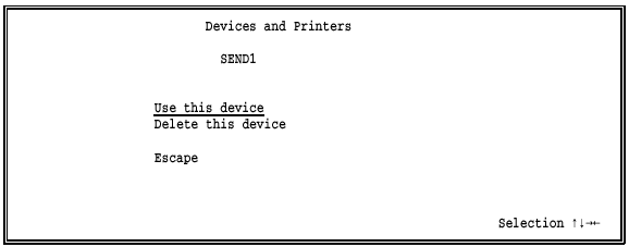
The same choices display for each SEND device.
Use this device
Default. Select this option to enable the SEND device. You must enable the device before you can use it. The selected SEND device displays as a source device on the Assign Devices screen. It becomes active as soon you assign it to a destination other than SUSPEND. Additionally, the Send Files command displays on the Operation screen.
Delete this device
Disable the SEND device and remove it from the Assign Devices screen. The status (deleted) displays next to the device name at the top of the screen. The Assign Devices screen is easier to read if you disable devices you do not intend to use. Additionally, the Send Files command is removed from the Operation screen.
Escape
Select Escape or press the ESC key to return to the Devices and Printers menu.
The Barr LAN devices let users on the network route files with BARR/RJE software. Network users can route their files to any BARR/RJE destination device. For example, they can submit jobs to the mainframe. Because this feature functions as if network users were connected to the Barr PC, it is called LAN connections.
A LAN device is a network directory that BARR/RJE checks at regular intervals. When it finds a file in the directory, BARR/RJE routes the file to the destination specified on the Assign Devices screen. You can specify up to four LAN devices and assign each device a different directory and a different destination.
After you enable a LAN device, you must define the options on the LAN Connection screen. Then users can copy files into the designated directory with the DOS copy command or Barr move utility.
You also can specify whether files are to be deleted or saved to another directory after they are sent.
 From the Devices and Printers menu, select a LAN device.
For example, select LAN1.
A list of options displays.
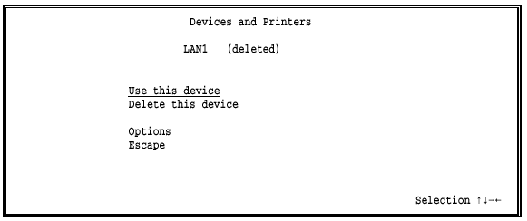
The same choices display for each LAN device.
Use this device
Enable the LAN device. You must select this option to enable the device. The selected LAN device displays as a source device on the Assign Devices screen. Before you can use the LAN device, you also must select Options and define a LAN connections directory.
Delete this device
Default. Disable the LAN device and remove it from the Assign Devices screen. The status (deleted) displays next to the device name at the top of the screen. The Assign Devices screen is easier to read if you disable devices you do not intend to use.
Options
To use the LAN device, you must specify additional options, including the LAN connections directory. See LAN Connection Options below.
Escape
Select Escape or press the ESC key to return to the Devices and Printers menu.
 From the LAN Connection screen for the selected LAN device,
select Options.
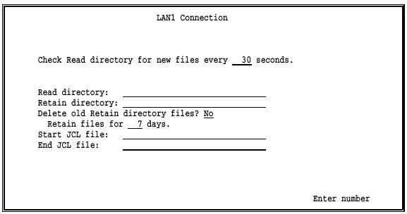
Check Read directory for new files every __ seconds:
Specify how often BARR/RJE checks all the LAN connections directories for files. The default interval is 30 seconds. You can adjust this value from any one of the LAN1 to LAN4 screens, and the change is reflected on all four screens.
Read directory:
Specify the name of the directory containing the files to be routed. Include the drive letter and the full directory path. You can specify a different directory for each LAN device. Files are removed from this directory after they are routed.
 If you only specify a drive letter, the current directory
will be used, not the root directory. To avoid confusion and potential
errors when you change the current directory, specify the complete file
path.
You can follow the directory name with a forward slash (/) and any of the send modes described in section 21.4.
 When you use LAN connections to send files to the host, BARR/RJE
interprets a pair of pound signs (##)
in a file as an embedded send files command. If your files contain pound
sign pairs that you do not want interpreted as send files commands, include
a backslash after the directory name followed by a /1 send mode (for example, c:\read\/1).
See section 21.4 for more
information about the embedded send files command.
Retain directory:
Optional. The name of the directory, including the drive letter, where files will be moved after they are routed. If no retain directory name is given, the files are deleted after they are routed. The retain directory must have the same drive letter as the read directory, because the two directories must reside on the same logical drive or partition. If a file with the same name already exists in the retain directory, a unique numeric file name extension will be added to the new file so it does not overwrite the existing file. See File Name Extensions in section 10.5 for more information.
 Do not confuse the LAN connection retain directory with the
print spool retain directory described in Chapter
9.
Delete old Retain directory files?
If you use the retain directory feature, choose whether old retain files will be automatically deleted. Use this feature to periodically free disk space when you retain a large number of files.
No Default. Retain files must be deleted manually. If you retain a large number of files, you should periodically delete the files from disk so the hard drive does not become full.
Yes Retain files are deleted automatically after the specified retain period has expired.
Retain files for __ days.
Specify the number of days that files will be retained before they are automatically deleted. The default retain period is 7 days. When files are moved to the retain directory, the date and time are changed to the current PC date and time to enable tracking of the retain period. The software deletes the expired retain files each time it starts and at midnight when the PC system date changes.
This option is valid only if Delete old Retain directory files is set to Yes.
Start JCL file:
Optional. The file is sent immediately before each file. This feature is often used to send Job Control Language (JCL) with files that will be submitted to the host as jobs. You must put the start file in a separate directory. When you specify the start file name, include the drive letter and full directory path.
End JCL file:
Optional. The specified file is sent immediately after each file. For example, you can send JCL at the end of a job. You must put the end file in a separate directory. When you specify the end file name, include the drive letter and full directory path.
When a file is sent from the LAN connections directory, the software
either deletes or renames the file. If an error occurs during the delete
or rename attempt, the LAN device is suspended (LAN1 SUSPEND) on
the Assign Devices screen. To re-enable the LAN device, you must correct
the error and then re-assign the device to its original destination from
the Assign Devices screen.
If you direct files from a LAN directory to the host (LAN1 RD1), the device is not suspended if the SNA
session is lost. When the host recovers, the LAN device continues to function
and does not require operator intervention.
The Barr move command changes the location of a file by renaming the directory portion of the file name. This method is faster than copying the file to a new location and then deleting the original file. The move command for MS-DOS version 6.0 automatically overwrites existing files. The Barr move command does not overwrite existing files unless you explicitly specify the overwrite option. The MOVE.EXE file is provided with the Barr reference files.
Follow these guidelines when you use the move command.
The form of the command is:
move f:\path1\file1 f:\path2\file2
where f: is the drive letter, path1 is the directory where the original file is located, file1 is the file name, path2 is the new directory for the file, and file2 is the new file name.
You can only move files to new locations on the same drive. (The new file location must have the same drive letter as the original file location.) For example:
move f:\jobs\payroll.001 f:\lan1\payroll.001
The move command supports moving multiple files with the DOS wildcard characters * and ?. For example:
move f:\jobs\pay*.* f:\lan1\*.*
You can rename the file when you move it. For example:
move f:\jobs\payroll.001 f:\lan1\checks.001
If a file with the same name already exists in the destination directory, the move command displays an error message. It does not overwrite the file.
To overwrite a file with the same name, use the /d switch. For example:
move/d f:\path1\file f:\path2\*.*
For online help with the move command, type move at the DOS prompt and press ENTER.
This example shows how to use LAN connections to submit jobs to the
mainframe from the local area network. To route files to the host, you
will assign LAN1 RD1 on Assign Devices screen. On the LAN1 Connection
screen, specify the options as follows:
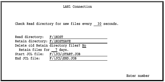
Assume you have prepared the file F:\WORK\DATA to send to the mainframe. To put the file in the LAN connections directory, enter this command at the DOS prompt:
move f:\work\data f:\host\*.*
When the software checks the directory at the next 30-second interval, it finds the file and adds the start and end JCL files as follows:
f:\jcl\start.job + f:\host\data + f:\jcl\end.job
The combined file is sent to the mainframe on reader 1 (RD1).
Because a retain directory is defined, BARR/RJE automatically moves the file F:\HOST\DATA to the directory F:\HOSTSAVE. If a file named DATA already exists in the F:\HOSTSAVE directory, the software assigns the file a unique numeric file extension.
You can receive data from Novell NetWare job or print queues if you set the options described in this section.
On the network, files are stored in queues until they are routed. Queues reside on network file servers. The Barr software must access the network queues to receive the waiting files. To do this, the software performs the function of a network queue server. It services the queues by logging into the file servers and retrieving the files. You can direct data received from the Novell queues to printers or route it to the mainframe as jobs.
The Novell network allows a PC to connect to a maximum of eight different file servers at a time.
If you use the Barr NOVELL Queues option, the software logs into one file server as a print server. This type of connection is different from the user connection made by the NET devices to access Novell print queues. The software will not log out of the print server connection during program operation.
Because Novell does not allow a PC to log into the same file server as both a user and a print server, the NET devices cannot access the same server used by the Novell queues (NW_QUEn).
Of the eight possible server connections, the number available for use by BARR/RJE depends on how many server connections are used for other purposes. The PC can log into file servers when you power it on, before the Barr software starts. These server connections are used to access network drives and cannot be logged out by the Barr software. The Barr LAN connections feature can use these connections. If you use the Barr NET devices to access Novell print queues, the software will log into and out of file servers as needed.
BARR/RJE supports banner pages at the beginning of jobs and form feeds at the end of jobs received on Novell NetWare queues. The Novell client software controls whether or not banner pages and form feeds are generated. Banner pages include the user name, queue name, file name, and other information that helps identify jobs. The banner page produced by BARR/RJE is similar to Novell banner pages, but the banner name and file name at the top of the banner page are in regular-sized type, rather than oversized type.
 From the Devices and Printers menu, select NOVELL Queues.
The following screen displays.
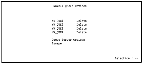
NW_QUE1-NW_QUE4
Select the Novell NetWare queue to use. When you press ENTER, another screen displays. Source Queue Options later in this section describes these options.
Queue Server Options
The Barr software acts as a network queue server. When you press ENTER, another screen displays. Queue Server Options later in this section describes these options.
When you select an NW_QUE device from the screen, the Source Queue Options screen displays. For example, the following screen displays if you select NW_QUE1:
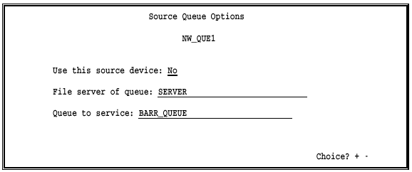
The same options display for each NW_QUE device.
Use this source device:
Select whether to enable the device.
No Default. Disable the device and remove it from the Assign Devices screen. The word Delete displays next to the queue name on the Novell Queue Devices screen.
Yes Enable the device and display it on the Assign Devices screen.
File server of queue:
Enter the name of the file server on which the queue is located. The queues can be located on the same file server or different file servers.
Queue to service:
Enter the name of the queue to be serviced by the Barr software.
The Barr software acts as a queue server on the network to access the Novell queues. You must specify a server name and password so the software can log into the necessary file servers.
When you select Queue Server Options, the following screen displays:
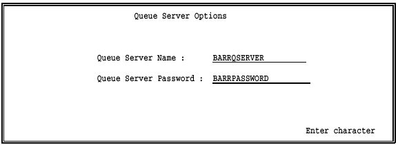
Queue Server Name:
Enter the server name assigned to the BARR/RJE software. This name is used to access the Novell queues.
Queue Server Password:
Enter the server password. BARR/RJE uses the password to access the Novell queues.
BARR/RJE supports printing multiple copies of files received from Novell NetWare queues.
If files are received to disk or to the print spool, their Novell job information can be copied to the Barr spool header. The Novell form name and copy count will be stored in the corresponding fields of the Barr spool header, and the Novell banner name will be stored as the job name.
To print multiple copies, the file must be received to the print spool. See Chapters 9 and 24 for more information about print spool setup and operation.